ENGINE
3.30
VALVE INSPECTION, CONT.
6.
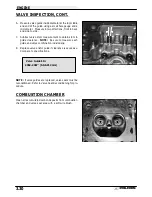
Measure valve guide inside diameter at the top middle
and end of the guide using a small hole gauge and a
micrometer. Measure in two directions, front to back
and side to side.
7.
Subtract valve stem measurement to obtain stem to
guide clearance. NOTE: Be sure to measure each
guide and valve combination individually.
8.
Replace valve and/or guide if clearance is excessive.
Compare to specifications.
NOTE: If valve guides are replaced, valve seats must be
reconditioned. Refer to Valve Seat Reconditioning for pro-
cedure.
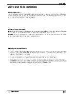
COMBUSTION CHAMBER
Clean all accumulated carbon deposits from combustion
chamber and valve seat area with a soft wire brush.
Valve Guide I.D.:
.2362-.2367
I
(6.0-6.012 mm)
Summary of Contents for Sportsman 400
Page 6: ...SPORTSMAN 400 A01CH42AC GENERAL INFORMATION 1 4 MODEL COLOR IDENTIFICATION ...
Page 21: ...Newton Meter to Pound Foot and Pound Inch GENERAL INFORMATION 1 19 TORQUE CONVERSIONS ...
Page 22: ...Newton Meter to Pound Foot and Pound Inch GENERAL INFORMATION 1 20 TORQUE CONVERSIONS ...
Page 152: ...Forward FUEL SYSTEM CARBURETION 4 2 FUEL TANK ASSEMBLY ...
Page 366: ...ELECTRONIC SPEEDOMETER WIRING DIAGRAM ELECTRICAL 10 32 ...
Page 372: ...ELECTRICAL 10 38 NOTES ...
Page 379: ...ELECTRICAL 10 39 WIRING DIAGRAM 2001 SPORTSMAN 400 ...
Page 380: ...ELECTRICAL 10 40 WIRING DIAGRAM 2001 SPORTSMAN 500 EARLY ...
Page 381: ...ELECTRICAL 10 41 WIRING DIAGRAM 2001 SPORTSMAN 500 LATE ...


