TRANSMISSION
8.6
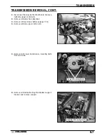
TRANSMISSION REMOVAL
All operations regarding transmission front output housing assembly can be performed with transmission installed
in frame.
1.
Remove the inner PVT cover. Refer to Clutch
Chapter.
2.
Remove
complete
airbox
assembly
and
transmission vent line.
3.
Loosen rear wheel nuts slightly.
4.
Elevate
and
support
machine
under
footrest/frame area.
CAUTION: Serious injury may result if machine tips
or falls. Be sure machine is secure before beginning
this service procedure. Wear eye protection when re-
moving and installing bearings and seals.
5.
Remove wheel nuts and wheels.
6.
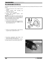
Apply hand and auxiliary brake and remove brake
disc retaining nut and washer. NOTE: Domed
side of washer faces nut.
7.
Remove rear (auxiliary) brake caliper and disc.
Support caliper on right hand foot rest.
8.
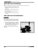
Disconnect
transmission
shift
linkage
rods.
Remove right hand shock absorber.
9.
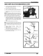
Disconnect harness from gear position switches.
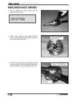
10. Remove right rear drive shaft (see page 7.32).
Domed side
toward nut
Pull outward to remove
from transmission
Summary of Contents for Sportsman 400
Page 6: ...SPORTSMAN 400 A01CH42AC GENERAL INFORMATION 1 4 MODEL COLOR IDENTIFICATION ...
Page 21: ...Newton Meter to Pound Foot and Pound Inch GENERAL INFORMATION 1 19 TORQUE CONVERSIONS ...
Page 22: ...Newton Meter to Pound Foot and Pound Inch GENERAL INFORMATION 1 20 TORQUE CONVERSIONS ...
Page 152: ...Forward FUEL SYSTEM CARBURETION 4 2 FUEL TANK ASSEMBLY ...
Page 366: ...ELECTRONIC SPEEDOMETER WIRING DIAGRAM ELECTRICAL 10 32 ...
Page 372: ...ELECTRICAL 10 38 NOTES ...
Page 379: ...ELECTRICAL 10 39 WIRING DIAGRAM 2001 SPORTSMAN 400 ...
Page 380: ...ELECTRICAL 10 40 WIRING DIAGRAM 2001 SPORTSMAN 500 EARLY ...
Page 381: ...ELECTRICAL 10 41 WIRING DIAGRAM 2001 SPORTSMAN 500 LATE ...


