BODY / STEERING / SUSPENSION
5.6
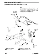
STEERING ASSEMBLY, EXPLODED VIEW
25-30 ft. lbs.
(35-41 Nm)
Loctite
™
242
8 ft. lbs.
(11 Nm)
25 ft. lbs.
(35 Nm)
30 ft. lbs.
41 Nm)
Always use new bolts
upon reassembly
Always use new cotter pins upon
reassembly. Install w/ open end to-
ward rear of machine.
B
1
2
1
30 ft. lbs.
41 Nm)
A
2
12-14 ft. lbs.
(17-17 Nm)
40-45 ft. lbs.
54-61 Nm)
Steering Post
Steering Post
Arm (Frog)
1
2
NOTE:
To avoid damage to tie rods and other steering
components, be sure to install tie rod end bolts in the
proper direction. The steering post arm bolt (B) points up;
the rod end bolts (A) point down. Be sure inner rod ends
are placed between the steering post arms.
Summary of Contents for Sportsman 400
Page 6: ...SPORTSMAN 400 A01CH42AC GENERAL INFORMATION 1 4 MODEL COLOR IDENTIFICATION ...
Page 21: ...Newton Meter to Pound Foot and Pound Inch GENERAL INFORMATION 1 19 TORQUE CONVERSIONS ...
Page 22: ...Newton Meter to Pound Foot and Pound Inch GENERAL INFORMATION 1 20 TORQUE CONVERSIONS ...
Page 152: ...Forward FUEL SYSTEM CARBURETION 4 2 FUEL TANK ASSEMBLY ...
Page 366: ...ELECTRONIC SPEEDOMETER WIRING DIAGRAM ELECTRICAL 10 32 ...
Page 372: ...ELECTRICAL 10 38 NOTES ...
Page 379: ...ELECTRICAL 10 39 WIRING DIAGRAM 2001 SPORTSMAN 400 ...
Page 380: ...ELECTRICAL 10 40 WIRING DIAGRAM 2001 SPORTSMAN 500 EARLY ...
Page 381: ...ELECTRICAL 10 41 WIRING DIAGRAM 2001 SPORTSMAN 500 LATE ...


