FINAL DRIVE
7.5
AWD FRONT HUB BEARING ADJUSTMENT
WARNING
The following bearing adjustments are very important. Incorrect adjustment will increase bearing wear, reduce
braking action, and may affect front drive hub engagement, which could result in serious personal injury or death.
1.
Torque spindle nut to 160-170 inch lbs. while
rotating hub continuously.
2.
Back off nut 1/2 turn.
3.
Rotate axle several revolutions by raising rear of
machine and rotating rear wheels with the
machine in gear.
4.
Re-torque hub nut to 108-144 inch lbs.
5.
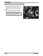
Install cotter pin.
Bend each leg of cotter pin
around castle nut in different directions.
See
below.
NOTE: If cotter pin hole does not align, tighten slightly
to align and install pin. Do not exceed 144 in. lbs.
6.
Reinstall hub cap.
7.
Remove fill check plug and rotate hole to either
4:00 or 8:00 position.
8.
Fill with Polaris Premium Demand Drive Hub Fluid
or Type F Automatic Transmission Fluid until fluid
trickles out. NOTE: Do not force the oil into the
hub under pressure. This can cause seal damage
and leaks.
9.
Reinstall plug.
10. Reinstall brake caliper assembly. Torque retaining
bolts to 18 ft. lbs. (25 Nm).
11. Reinstall front wheels. Torque retaining nuts to 15
ft. lbs. (21 Nm).
12. Carefully lower vehicle.
13. Field test vehicle for proper operation of brake
system and AWD operation.
Front Spindle Nut Torque:
108-144 in. lbs.
Brake Caliper Retaining Bolt Torque:
18 ft. lbs. (25 Nm)
Premium Demand Drive Hub Fluid
PN 2871654 (8 oz.)
PN 2872277 (2.5 gal.)
Summary of Contents for Sportsman 400
Page 6: ...SPORTSMAN 400 A01CH42AC GENERAL INFORMATION 1 4 MODEL COLOR IDENTIFICATION ...
Page 21: ...Newton Meter to Pound Foot and Pound Inch GENERAL INFORMATION 1 19 TORQUE CONVERSIONS ...
Page 22: ...Newton Meter to Pound Foot and Pound Inch GENERAL INFORMATION 1 20 TORQUE CONVERSIONS ...
Page 152: ...Forward FUEL SYSTEM CARBURETION 4 2 FUEL TANK ASSEMBLY ...
Page 366: ...ELECTRONIC SPEEDOMETER WIRING DIAGRAM ELECTRICAL 10 32 ...
Page 372: ...ELECTRICAL 10 38 NOTES ...
Page 379: ...ELECTRICAL 10 39 WIRING DIAGRAM 2001 SPORTSMAN 400 ...
Page 380: ...ELECTRICAL 10 40 WIRING DIAGRAM 2001 SPORTSMAN 500 EARLY ...
Page 381: ...ELECTRICAL 10 41 WIRING DIAGRAM 2001 SPORTSMAN 500 LATE ...


