ELECTRICAL
10.35
FAN MOTOR CURRENT DRAW
A current draw test will provide a good indication of fan
motor condition. A worn or damaged fan motor will draw
more current, which causes a reduction in blade speed
and reduced cooling.
1.
Disconnect the Red/White wire from the fan motor.
2.
Connect a DC ammeter in series between the
battery and fan motor as shown at right. Use the
Red/White wire in the wiring harness as the power
supply.
3.
Be sure fan blade is free to rotate.
4.
Turn ignition key and engine stop switch to “ON”
position. Read the current draw on ammeter with
fan running.
5.
If the fan motor draws more than 6.5 Amps, replace
the motor.
BRAKE LIGHT SWITCH
1.
Remove fuel tank.
2.
Disconnect wire harness from switch.
3.
Connect an ohmmeter across switch contacts. Reading should be infinite (
∞
).
4.
Apply brake at handlebar lever and check for continuity between switch contacts. Replace switch if there is no
continuity or greater than .5 ohms resistance when the brake is applied with slight pressure.
HEADLAMP SWITCH
Remove the headlight pod cover. Probe the headlamp plug wires (Brown and Yellow) at back of connector. Turn
headlight on. Test for battery voltage across the connections.
NEUTRAL LIGHT CIRCUIT OPERATION
Power is supplied to the transmission switch from the Red/White wire when the key is on. When neutral is se-
lected, power flows through the switch to the Green/White wire, through the lamp and to ground via the Brown
wire.
If the light is not on when neutral is selected, check the bulb. If the bulb is good, check the wiring, transmission
switch, and lamp socket ground path.
Fan Motor
Brn
R/W
Connect ammeter to
R/W wire (battery power
side) of wiring harness.
Fan Switch
Fan Motor Current Draw:
Less Than 6.5 Amps
Summary of Contents for Sportsman 400
Page 6: ...SPORTSMAN 400 A01CH42AC GENERAL INFORMATION 1 4 MODEL COLOR IDENTIFICATION ...
Page 21: ...Newton Meter to Pound Foot and Pound Inch GENERAL INFORMATION 1 19 TORQUE CONVERSIONS ...
Page 22: ...Newton Meter to Pound Foot and Pound Inch GENERAL INFORMATION 1 20 TORQUE CONVERSIONS ...
Page 152: ...Forward FUEL SYSTEM CARBURETION 4 2 FUEL TANK ASSEMBLY ...
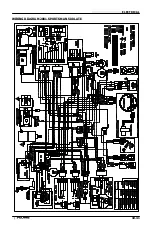
Page 366: ...ELECTRONIC SPEEDOMETER WIRING DIAGRAM ELECTRICAL 10 32 ...
Page 372: ...ELECTRICAL 10 38 NOTES ...
Page 379: ...ELECTRICAL 10 39 WIRING DIAGRAM 2001 SPORTSMAN 400 ...
Page 380: ...ELECTRICAL 10 40 WIRING DIAGRAM 2001 SPORTSMAN 500 EARLY ...
Page 381: ...ELECTRICAL 10 41 WIRING DIAGRAM 2001 SPORTSMAN 500 LATE ...

