TRANSMISSION
8.5
GEAR SHIFT SELECTOR INSTALLATION
1.
Place gear shift selector back into the mounting
bracket and replace five bolts.
2.
Reconnect linkage rods to gear shift selector
slides.
Adjust as required.
See linkage
adjustment procedures.
3.
Replace remaining parts.
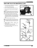
BOOT REPLACEMENT
NOTE: If moisture is found in the gear shift selector
the boot should be replaced.
1.
Using a slotted screwdriver, remove cap from
gear shift knob.
2.
Remove torx screw securing knob to selector
rod.
3.
Pull selector knob off selector rod.
4.
Remove band clamp on rubber boot.
5.
Slide boot off selector rod and replace with a
new one.
6.
Apply RTV silicone to selector rod to seal top of
boot.
7.
Place band clamp in position and tighten using
CV boot clamp pliers.
8.
Replace shift knob, securing it to selector rod
with screw removed in step 2.
9.
Push shift knob cover back into place. Allow
approximately 12 hours for RTV silicone to cure.
Knob
Screw
Cap
Clamp
Boot
Seal with
RTV silicone
Summary of Contents for Sportsman 400
Page 6: ...SPORTSMAN 400 A01CH42AC GENERAL INFORMATION 1 4 MODEL COLOR IDENTIFICATION ...
Page 21: ...Newton Meter to Pound Foot and Pound Inch GENERAL INFORMATION 1 19 TORQUE CONVERSIONS ...
Page 22: ...Newton Meter to Pound Foot and Pound Inch GENERAL INFORMATION 1 20 TORQUE CONVERSIONS ...
Page 152: ...Forward FUEL SYSTEM CARBURETION 4 2 FUEL TANK ASSEMBLY ...
Page 366: ...ELECTRONIC SPEEDOMETER WIRING DIAGRAM ELECTRICAL 10 32 ...
Page 372: ...ELECTRICAL 10 38 NOTES ...
Page 379: ...ELECTRICAL 10 39 WIRING DIAGRAM 2001 SPORTSMAN 400 ...
Page 380: ...ELECTRICAL 10 40 WIRING DIAGRAM 2001 SPORTSMAN 500 EARLY ...
Page 381: ...ELECTRICAL 10 41 WIRING DIAGRAM 2001 SPORTSMAN 500 LATE ...


