CLUTCH
6.18
DRIVE CLUTCH ASSEMBLY, CONT.
8.
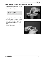
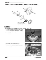
Reinstall cover, aligning “X” mark with other marks.
Torque cover bolts evenly to specification.
DRIVE BELT TENSION
NOTE: Pinch the sheaves lightly together with clamp to prevent the belt from being pushed into the driven sheave.
1.
Place a straight edge on top of the belt between drive and
driven clutch.
2.
Push down on drive belt until it is lightly tensioned.
3.
Measure belt deflection as shown in photo.
If belt deflection is out of specification, adjust by removing or
adding shims between the driven clutch sheaves.
S
Remove shims to decrease belt deflection
S
Add shims to increase belt deflection
See Driven Clutch Disassembly/Inspection, pages 6.26 -
6.28.
NOTE: At least one shim must remain between the inner and
outer sheave of the driven clutch. If proper belt deflection
cannot be obtained, measure drive belt width, length, and
center distance of drive and driven clutch, outlined in this sec-
tion; all have an effect on belt deflection.
Spider Torque:
200 ft. lbs. (276 Nm)
Cover Screw Torque:
90 in. lbs. (10.4 Nm)
1 1/8
″
(28.5 mm)
Straight Edge
Belt Deflection (Tension):
1 1/8
″
(2.9 cm) - 1 1/4
″
(3.2 cm)
Summary of Contents for Sportsman 400
Page 6: ...SPORTSMAN 400 A01CH42AC GENERAL INFORMATION 1 4 MODEL COLOR IDENTIFICATION ...
Page 21: ...Newton Meter to Pound Foot and Pound Inch GENERAL INFORMATION 1 19 TORQUE CONVERSIONS ...
Page 22: ...Newton Meter to Pound Foot and Pound Inch GENERAL INFORMATION 1 20 TORQUE CONVERSIONS ...
Page 152: ...Forward FUEL SYSTEM CARBURETION 4 2 FUEL TANK ASSEMBLY ...
Page 366: ...ELECTRONIC SPEEDOMETER WIRING DIAGRAM ELECTRICAL 10 32 ...
Page 372: ...ELECTRICAL 10 38 NOTES ...
Page 379: ...ELECTRICAL 10 39 WIRING DIAGRAM 2001 SPORTSMAN 400 ...
Page 380: ...ELECTRICAL 10 40 WIRING DIAGRAM 2001 SPORTSMAN 500 EARLY ...
Page 381: ...ELECTRICAL 10 41 WIRING DIAGRAM 2001 SPORTSMAN 500 LATE ...

