ELECTRICAL
10.33
COOLANT TEMPERATURE SENSOR TEST (HOT LIGHT)
With the ignition switch (and engine stop switch) “ON”, power is delivered to the hot light via the Red/White wire.
The Blue/White wire (ground) out of the light socket is connected to the coolant temperature sensor on the cylinder
head. In normal operating conditions, the temperature sensor is non-conductive (open). If engine coolant reach-
es the specified temperature, the sensor becomes conductive completing the ground path for the light.
With engine cold, disconnect lead and measure resistance of sensor between connector terminal and ground.
There should be no continuity or very high resistance (megohms). To test the “ON” temperature, heat the switch
in a water bath to the temperature shown in table below. The switch should become conductive (low resistance)
at indicated temperature. Do not immerse switch past the threads or allow switch to contact container when heat-
ing.
Hot Light On
221
°
F (105
°
C)
HOT LIGHT CIRCUIT TEST
Disconnect temperature sensor wire lead and short it to ground on the cylinder head. Turn key and auxiliary switch
to “ON” position. The hot lamp should come on. Check the bulb and related wiring if the lamp does not illuminate.
Summary of Contents for Sportsman 400
Page 6: ...SPORTSMAN 400 A01CH42AC GENERAL INFORMATION 1 4 MODEL COLOR IDENTIFICATION ...
Page 21: ...Newton Meter to Pound Foot and Pound Inch GENERAL INFORMATION 1 19 TORQUE CONVERSIONS ...
Page 22: ...Newton Meter to Pound Foot and Pound Inch GENERAL INFORMATION 1 20 TORQUE CONVERSIONS ...
Page 152: ...Forward FUEL SYSTEM CARBURETION 4 2 FUEL TANK ASSEMBLY ...
Page 366: ...ELECTRONIC SPEEDOMETER WIRING DIAGRAM ELECTRICAL 10 32 ...
Page 372: ...ELECTRICAL 10 38 NOTES ...
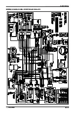
Page 379: ...ELECTRICAL 10 39 WIRING DIAGRAM 2001 SPORTSMAN 400 ...
Page 380: ...ELECTRICAL 10 40 WIRING DIAGRAM 2001 SPORTSMAN 500 EARLY ...
Page 381: ...ELECTRICAL 10 41 WIRING DIAGRAM 2001 SPORTSMAN 500 LATE ...


