FINAL DRIVE
7.9
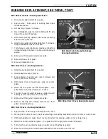
HILLIARD CLUTCH DISASSEMBLY/INSPECTION
1.
Remove front hub. See page 7.3.
2.
Remove Hilliard clutch assembly.
3.
Disassemble the roller clutch and thoroughly clean all parts. CAUTION: Do not remove the garter spring. If
the spring is removed, it will become over stressed and will require replacement.
4.
Inspect roll cage sliding surface (A). This surface must be clean and free of nicks, burrs or scratches. Inspect
roller cage (2) carefully for cracks.
5.
Inspect rollers (3). The rollers must slide up and down freely within the roller cage sliding surfaces A.
6.
Without removing the garter spring,
inspect the coils for consistency. If
coils are distorted or uneven, cut the
old spring with a side cutter to remove
it, and replace it.
7.
If garter spring replacement is necessary, it is very
important that the correct installation procedure
and special tool be used. Hold rollers in place on
roller cage with a light film of grease. Gently and
evenly roll the spring down the tapered tool (PN
2870888) and into the groove of the rollers and
cage. WARNING: If this procedure is not followed
the spring will be over stressed and lose its tension.
Springs with incorrect tension may allow rollers to
move outward at high vehicle speeds. If the rollers
move outward, the front hub(s) will engage and
cause vehicle instability, which could result in
serious injury or death.
WARNING:
Be sure to use correct garter spring.
These springs are very similar in appearance to those
used on earlier models. If the old, lighter springs were
installed on a machine requiring the heavier spring, the
front wheels may engage at high speed, possibly re-
sulting in serious injury or death. Check springs be-
fore installation. Always verify the correct replace-
ment spring part number by referring to the
appropriate parts manual.
Current electro-mechanical spring, PN 3250032; wire
diameter .018
″
(.46 mm); spring free length end to end
inside hooks 6.968
″
(177 mm).
1
2
3
5
4
A
Engage tabs in the slots
1. Armature Plate NOTE: Armature plate is positioned with
tabs in round holes of cage.
2. Roller Cage
3. Roller
4. Garter Spring
5. Cam
Spacer
Inspect for cracks
Must use tool to install garter spring
PN 2870888
Measure wire diameter
Measure free length to inside of
loops as shown
Summary of Contents for Sportsman 400
Page 6: ...SPORTSMAN 400 A01CH42AC GENERAL INFORMATION 1 4 MODEL COLOR IDENTIFICATION ...
Page 21: ...Newton Meter to Pound Foot and Pound Inch GENERAL INFORMATION 1 19 TORQUE CONVERSIONS ...
Page 22: ...Newton Meter to Pound Foot and Pound Inch GENERAL INFORMATION 1 20 TORQUE CONVERSIONS ...
Page 152: ...Forward FUEL SYSTEM CARBURETION 4 2 FUEL TANK ASSEMBLY ...
Page 366: ...ELECTRONIC SPEEDOMETER WIRING DIAGRAM ELECTRICAL 10 32 ...
Page 372: ...ELECTRICAL 10 38 NOTES ...
Page 379: ...ELECTRICAL 10 39 WIRING DIAGRAM 2001 SPORTSMAN 400 ...
Page 380: ...ELECTRICAL 10 40 WIRING DIAGRAM 2001 SPORTSMAN 500 EARLY ...
Page 381: ...ELECTRICAL 10 41 WIRING DIAGRAM 2001 SPORTSMAN 500 LATE ...

