ELECTRICAL
10.19
STARTER SYSTEM
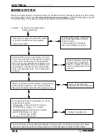
Condition: Starter fails to turn motor. NOTE: Make sure engine crankshaft is free to turn before proceeding with
dynamic testing of starter system. A digital multitester must be used for this test.
With the tester on the VDC position, place the tes-
ter’s black lead on the battery negative and the red
lead on the battery positive.
Reading should be 12.4 or greater.
Remove battery and properly service.
Install fully charged shop battery to continue
test.
Disconnect White/Red engagement coil wire from
the starter solenoid. Connect tester black wire to
battery ground. Connect red tester lead to White/
Red harness wire at solenoid. Turn on ignition
switch and depress the starter button. Tester
should read battery voltage.
Check voltage on both sides of circuit
breaker, ignition switch/engine stop switch
and starter button. The voltage on both
sides should be the same. NOTE: The igni-
tion switch and engine stop switch must be
on and the starter button depressed. Re-
place the defective component.
Reconnect the solenoid. Connect the tester black
lead to the battery positive and the red lead to the
solenoid end of the battery-to-solenoid wire. De-
press starter button. Reading should be less than
.1 V D.C.
Clean the battery-to-solenoid cable ends or
replace the cable.
Connect the black tester lead to solenoid end of
battery-to-solenoid cable. Connect red tester lead
to solenoid end of solenoid-to-starter cable. De-
press starter button. Reading should be less than
.1 V D.C.
Replace the starter solenoid.
Connect the black tester lead to the solenoid end of
the solenoid-to-starter cable. Connect the red tester
lead to the starter end of the same cable. Depress
the starter button. The reading should be less than
.1 V D.C.
Clean the solenoid-to-starter cable ends or
replace the cable.
No
Yes
No
No
Yes
No
Yes
If all of these indicate a good condition, yet the starter still fails to turn, the
starter must be removed for static testing and inspection.
No
Yes
Test starter solenoid coil by connecting an ohmmeter between the solenoid
red wire and the solenoid mounting plate. Resistance should be 3.4
Ω
.
Check solenoid ground path by measuring resistance between mounting
plate and battery negative terminal (-).
Voltage Drop Testing
See Page 10.18 for instructions.
Yes
Summary of Contents for Sportsman 400
Page 6: ...SPORTSMAN 400 A01CH42AC GENERAL INFORMATION 1 4 MODEL COLOR IDENTIFICATION ...
Page 21: ...Newton Meter to Pound Foot and Pound Inch GENERAL INFORMATION 1 19 TORQUE CONVERSIONS ...
Page 22: ...Newton Meter to Pound Foot and Pound Inch GENERAL INFORMATION 1 20 TORQUE CONVERSIONS ...
Page 152: ...Forward FUEL SYSTEM CARBURETION 4 2 FUEL TANK ASSEMBLY ...
Page 366: ...ELECTRONIC SPEEDOMETER WIRING DIAGRAM ELECTRICAL 10 32 ...
Page 372: ...ELECTRICAL 10 38 NOTES ...
Page 379: ...ELECTRICAL 10 39 WIRING DIAGRAM 2001 SPORTSMAN 400 ...
Page 380: ...ELECTRICAL 10 40 WIRING DIAGRAM 2001 SPORTSMAN 500 EARLY ...
Page 381: ...ELECTRICAL 10 41 WIRING DIAGRAM 2001 SPORTSMAN 500 LATE ...


