ELECTRICAL
10.21
STARTER MOTOR DISASSEMBLY, CONT.
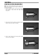
4.
Remove shims from armature shaft. NOTE: All shims
must be replaced during reassembly.
BRUSH INSPECTION/REPLACEMENT
1.
Using a digital multitester, measure the resistance
between the cable terminal and the insulated brush. The
reading should be .3 ohms or less.
Measure the
resistance between the cable terminal and brush
housing. Make sure the brush is not touching the case.
The reading should be infinite.
2.
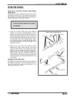
Remove nut, flat washer, large phenolic washer, two
small phenolic washers, and O-Ring from brush
terminal. Inspect the O-Ring and replace if damaged.
3.
Remove brush plate and brushes. Measure length of
brushes and replace if worn past the service limit.
Replace springs if they are discolored or have
inadequate tension.
4.
Inspect surface of commutator for wear or discoloration.
See steps 3-6 of armature testing on page 10.23.
5.
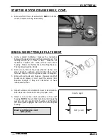
Install a new carbon brush assembly in the brush
housing. NOTE: Be sure that the terminal bolt insulating
washer is properly seated in the housing, and the tab on
the brush plate engages the notch in the brush plate
housing.
Brush Length Service Limit:
5/16
″
(.8 cm)
Brush Length
5/16
″
(.8 cm)
Summary of Contents for Sportsman 400
Page 6: ...SPORTSMAN 400 A01CH42AC GENERAL INFORMATION 1 4 MODEL COLOR IDENTIFICATION ...
Page 21: ...Newton Meter to Pound Foot and Pound Inch GENERAL INFORMATION 1 19 TORQUE CONVERSIONS ...
Page 22: ...Newton Meter to Pound Foot and Pound Inch GENERAL INFORMATION 1 20 TORQUE CONVERSIONS ...
Page 152: ...Forward FUEL SYSTEM CARBURETION 4 2 FUEL TANK ASSEMBLY ...
Page 366: ...ELECTRONIC SPEEDOMETER WIRING DIAGRAM ELECTRICAL 10 32 ...
Page 372: ...ELECTRICAL 10 38 NOTES ...
Page 379: ...ELECTRICAL 10 39 WIRING DIAGRAM 2001 SPORTSMAN 400 ...
Page 380: ...ELECTRICAL 10 40 WIRING DIAGRAM 2001 SPORTSMAN 500 EARLY ...
Page 381: ...ELECTRICAL 10 41 WIRING DIAGRAM 2001 SPORTSMAN 500 LATE ...


