TRANSMISSION
8.3
GEAR SHIFT SELECTOR DISASSEMBLY, CONT.
2.
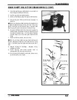
Carefully pull the gear shift selector cover and rod
from the gear shift selector body.
3.
Set the cover/rod assembly aside.
4.
Remove the three springs from gear shift selector.
5.
Slowly tilt gear shift selector body sideways to
drain oil.
NOTE: Do not tip gear shift selector body upside down
or detent bullets and stop pin may fall out. Check for
signs of moisture in the selector body. Inspect shift
boot closely if moisture is present in selector box.
6.
Tap gear shift selector body, top down, against a
hard, smooth, flat surface to jar the dowel pin and
two detent bullets loose. Pull the detent bullets
and the dowel pin out of the gear shift selector
body.
7.
Remove the two slides, one at a time.
NOTE: The LH (low) slide has two short notches and
the RH (high/rev) slide has one short and one long
notch. The slides must be replaced in the proper chan-
nels.
8.
Inspect O-rings for damage.
Replace if any
damage is found.
9.
Flush
housing
with
parts
washer
fluid
or
penetrating oil to remove all moisture.
10. Dry all gear shift selector parts and remove any
corrosion with a wire brush.
Knob
Screw
Cap
Clamp
Boot
Cover (Apply
Loctite
™
515)
Dowel
Pin
Handle
Selector Slides
Low
2 Short
Notches
High/Reverse
(1 Short,
1 Long Notch)
Detent Spring
Detent
Bullet
Centering Spring
Plastic
Sphere
Detent
Spring
Detent
Bullet
Groove
Pin
Summary of Contents for Sportsman 400
Page 6: ...SPORTSMAN 400 A01CH42AC GENERAL INFORMATION 1 4 MODEL COLOR IDENTIFICATION ...
Page 21: ...Newton Meter to Pound Foot and Pound Inch GENERAL INFORMATION 1 19 TORQUE CONVERSIONS ...
Page 22: ...Newton Meter to Pound Foot and Pound Inch GENERAL INFORMATION 1 20 TORQUE CONVERSIONS ...
Page 152: ...Forward FUEL SYSTEM CARBURETION 4 2 FUEL TANK ASSEMBLY ...
Page 366: ...ELECTRONIC SPEEDOMETER WIRING DIAGRAM ELECTRICAL 10 32 ...
Page 372: ...ELECTRICAL 10 38 NOTES ...
Page 379: ...ELECTRICAL 10 39 WIRING DIAGRAM 2001 SPORTSMAN 400 ...
Page 380: ...ELECTRICAL 10 40 WIRING DIAGRAM 2001 SPORTSMAN 500 EARLY ...
Page 381: ...ELECTRICAL 10 41 WIRING DIAGRAM 2001 SPORTSMAN 500 LATE ...


