CLUTCH
6.5
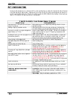
PVT DISASSEMBLY
NOTE: Some fasteners and procedures will vary. Refer to the appropriate parts manual for proper fasteners and
fastener placement. (See page 6.8).
1.
Remove seat.
2.
Remove or loosen rear cab fasteners as necessary to
gain access to PVT outer cover.
3.
Remove PVT air outlet duct hose.
4.
Remove outer cover screws and clip. Refer to page
6.8.
5.
Mark the drive belt direction of rotation and remove
drive belt. See page 6.19 for drive belt removal.
6.
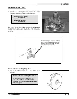
Remove drive clutch retaining bolt and remove drive
clutch using puller.
Drive Clutch Puller PN 2870506
Summary of Contents for Sportsman 400
Page 6: ...SPORTSMAN 400 A01CH42AC GENERAL INFORMATION 1 4 MODEL COLOR IDENTIFICATION ...
Page 21: ...Newton Meter to Pound Foot and Pound Inch GENERAL INFORMATION 1 19 TORQUE CONVERSIONS ...
Page 22: ...Newton Meter to Pound Foot and Pound Inch GENERAL INFORMATION 1 20 TORQUE CONVERSIONS ...
Page 152: ...Forward FUEL SYSTEM CARBURETION 4 2 FUEL TANK ASSEMBLY ...
Page 366: ...ELECTRONIC SPEEDOMETER WIRING DIAGRAM ELECTRICAL 10 32 ...
Page 372: ...ELECTRICAL 10 38 NOTES ...
Page 379: ...ELECTRICAL 10 39 WIRING DIAGRAM 2001 SPORTSMAN 400 ...
Page 380: ...ELECTRICAL 10 40 WIRING DIAGRAM 2001 SPORTSMAN 500 EARLY ...
Page 381: ...ELECTRICAL 10 41 WIRING DIAGRAM 2001 SPORTSMAN 500 LATE ...


