ENGINE
3.33
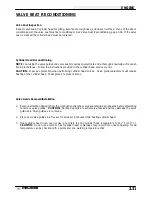
VALVE SEAT RECONDITIONING, CONT.
1.
Install pilot into valve guide.
2.
Apply cutting oil to valve seat and cutter.
3.
Place 46
°
cutter on the pilot and make a light cut.
4.
Inspect the cut area of the seat.
S
If the contact area is less than 75% of the cir-
cumference of the seat, rotate the pilot 180
°
and make another light cut.
S
If the cutter now contacts the uncut portion of
the seat, check the pilot. Look for burrs,
nicks, or runout. If the pilot is bent it must be
replaced.
S
If the contact area of the cutter is in the same
place, the valve guide is distorted from im-
proper installation and must be replaced. Be
sure the cylinder head is at the proper temper-
ature and replace the guide.
S
If the contact area of the initial cut is greater
than 75%, continue to cut the seat until all pits
are removed and a new seat surface is evi-
dent. NOTE: Remove only the amount of
material necessary to repair the seat surface.
5.
To check the contact area of the seat on the valve
face, apply a thin coating of Prussian Blue
™
paste to
the valve seat. If using an interference angle (46
°
)
apply black permanent marker to the entire valve
face (A).
6.
Insert valve into guide and tap valve lightly into place
a few times.
(A)
Summary of Contents for Sportsman 400
Page 6: ...SPORTSMAN 400 A01CH42AC GENERAL INFORMATION 1 4 MODEL COLOR IDENTIFICATION ...
Page 21: ...Newton Meter to Pound Foot and Pound Inch GENERAL INFORMATION 1 19 TORQUE CONVERSIONS ...
Page 22: ...Newton Meter to Pound Foot and Pound Inch GENERAL INFORMATION 1 20 TORQUE CONVERSIONS ...
Page 152: ...Forward FUEL SYSTEM CARBURETION 4 2 FUEL TANK ASSEMBLY ...
Page 366: ...ELECTRONIC SPEEDOMETER WIRING DIAGRAM ELECTRICAL 10 32 ...
Page 372: ...ELECTRICAL 10 38 NOTES ...
Page 379: ...ELECTRICAL 10 39 WIRING DIAGRAM 2001 SPORTSMAN 400 ...
Page 380: ...ELECTRICAL 10 40 WIRING DIAGRAM 2001 SPORTSMAN 500 EARLY ...
Page 381: ...ELECTRICAL 10 41 WIRING DIAGRAM 2001 SPORTSMAN 500 LATE ...

