BODY / STEERING / SUSPENSION
5.7
A-ARM REPLACEMENT
1.
Elevate and safely support vehicle with weight removed from front wheel(s).
2.
Remove cotter pin from ball joint stud at wheel end of A-arm and loosen nut until it is flush with end of stud.
3.
Using a soft face hammer, tap nut to loosen A-arm from bolt. Remove nut and A-arm from hub strut assembly.
4.
Loosen two bolts on A-arm tube by alternating each about 1/3 of the way until A-arm can be removed.
5.
Examine A-arm shaft. Replace if worn. Discard hardware.
6.
Insert A-arm shaft into new A-arm. NOTE: On AWD models, install CV joint shields. See Ill.
7.
Install new A-arm assembly onto vehicle frame. Torque new bolts to 30 ft. lbs. (41.4 Nm).
WARNING
The locking features on the existing bolts were destroyed
during removal. DO NOT reuse old bolts. Serious injury
or death could result if fasteners come loose during opera-
tion.
8.
Attach A-arm to hub strut assembly. Tighten ball joint
nut to 25 ft. lbs. (35 Nm). If cotter pin holes are not
aligned, tighten nut slightly to align. Install a new cotter
pin with open ends toward rear of machine. Bend both
ends in opposite directions around nut.
9.
Locate grease fitting in center of A-arm tube and pump
A-arm full of grease.
WARNING
Upon A-arm installation completion, test vehicle at low speeds before putting into regular service.
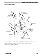
Vehicle Frame
Grease Fitting
Nut
Cotter Pin
Ball Joint
Stud
CV Joint Shield
(AWD Models)
A-Arm Tube
A-Arm Shaft
Bolt 30 ft. lbs.
(41 Nm)
Washer
25 ft. lbs
(35 Nm).
Loctite
™
242
8 ft. lbs.
(11 Nm)
Bolt 30 ft. lbs.
(41 Nm)
A-arm Attaching Bolt Torque:
30 ft. lbs. (41 Nm)
Ball Joint Stud Nut Torque:
25 ft. lbs. (35 Nm)
Summary of Contents for Sportsman 400
Page 6: ...SPORTSMAN 400 A01CH42AC GENERAL INFORMATION 1 4 MODEL COLOR IDENTIFICATION ...
Page 21: ...Newton Meter to Pound Foot and Pound Inch GENERAL INFORMATION 1 19 TORQUE CONVERSIONS ...
Page 22: ...Newton Meter to Pound Foot and Pound Inch GENERAL INFORMATION 1 20 TORQUE CONVERSIONS ...
Page 152: ...Forward FUEL SYSTEM CARBURETION 4 2 FUEL TANK ASSEMBLY ...
Page 366: ...ELECTRONIC SPEEDOMETER WIRING DIAGRAM ELECTRICAL 10 32 ...
Page 372: ...ELECTRICAL 10 38 NOTES ...
Page 379: ...ELECTRICAL 10 39 WIRING DIAGRAM 2001 SPORTSMAN 400 ...
Page 380: ...ELECTRICAL 10 40 WIRING DIAGRAM 2001 SPORTSMAN 500 EARLY ...
Page 381: ...ELECTRICAL 10 41 WIRING DIAGRAM 2001 SPORTSMAN 500 LATE ...


