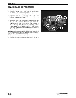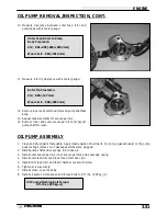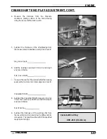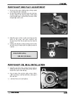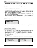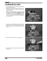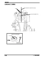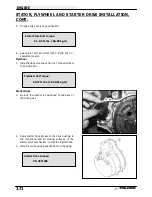
Ill. 3
Puller Legs
Ill. 4
Position the split
90
°
to opening
on main puller
body
Main puller
body
Hex Socket Screws
Ill. 5
Lip must grasp inside
of mechanical seal.
Puller Legs
Ill. 6
ENGINE
3.62
WATER PUMP MECHANICAL SEAL REMOVAL - ENGINE
INSTALLED, CONT.
3.
Insert the puller legs between the water pump drive
shaft and the remaining portion of the mechanical seal.
Attach the puller legs to the main puller body. Ill. 3
4.
Ensure that the split between the puller legs is fully sup-
ported by the main body of the tool (Ill 4).
5.
Tighten the hex socket screws on the puller legs suffi-
ciently so the lip of the puller legs will grasp the me-
chanical seal. Ill. 5
6.
Turn the puller T-Handle clockwise until it contacts the
water pump shaft. Continue rotating until the remaining
portion of mechanical seal has been removed from the
cases. Ill. 6 Pump shaft oil seal can also be replaced
at this time if necessary.
7.
Special tool (PN 5131135) is required to install the new
mechanical seal. This tool is available separately and
it is also included in the Crankshaft/Water Pump Seal
Installation Kit (PN 2871283).
Summary of Contents for Sportsman 400
Page 6: ...SPORTSMAN 400 A01CH42AC GENERAL INFORMATION 1 4 MODEL COLOR IDENTIFICATION ...
Page 21: ...Newton Meter to Pound Foot and Pound Inch GENERAL INFORMATION 1 19 TORQUE CONVERSIONS ...
Page 22: ...Newton Meter to Pound Foot and Pound Inch GENERAL INFORMATION 1 20 TORQUE CONVERSIONS ...
Page 152: ...Forward FUEL SYSTEM CARBURETION 4 2 FUEL TANK ASSEMBLY ...
Page 366: ...ELECTRONIC SPEEDOMETER WIRING DIAGRAM ELECTRICAL 10 32 ...
Page 372: ...ELECTRICAL 10 38 NOTES ...
Page 379: ...ELECTRICAL 10 39 WIRING DIAGRAM 2001 SPORTSMAN 400 ...
Page 380: ...ELECTRICAL 10 40 WIRING DIAGRAM 2001 SPORTSMAN 500 EARLY ...
Page 381: ...ELECTRICAL 10 41 WIRING DIAGRAM 2001 SPORTSMAN 500 LATE ...

