ENGINE
3.51
OIL PUMP REMOVAL/INSPECTION, CONT.
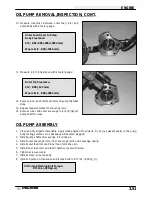
10. Measure clearance between outer feed rotor and
pump body with a feeler gauge.
11. Measure rotor tip clearance with a feeler gauge.
12. Remove inner and outer feed rotor and pump chamber
body.
13. Repeat measurements for scavenge rotor.
14. Remove inner and outer scavenge rotor and inspect
pump shaft for wear.
OIL PUMP ASSEMBLY
1.
Clean and dry all parts thoroughly. Apply clean engine oil to all parts. Do not use gasket sealer on the pump
body mating surfaces or oil passages will become plugged.
2.
Install pump shaft and scavenge rotor drive pin.
3.
Install outer scavenge rotor, inner scavenge rotor, and scavenge casing.
4.
Install outer feed rotor and inner feed rotor drive pin.
5.
Install inner feed rotor and feed chamber cover with screw.
6.
Tighten screw securely.
7.
Install screen on pump body.
8.
Install oil pump on crankcase and torque bolts to 6 ft. lbs. (.828 kg-m).
Outer Feed Rotor to Pump
Body Clearance:
Std: .001-.003 (.0254-.0762 mm)
Wear Limit: .004 (.1016 mm)
Rotor Tip Clearance:
Std: .005 (.127 mm)
Wear Limit: .008 (.2032 mm)
Oil Pump Attaching Bolt Torque:
6 ft. lbs. (.828 kg-m)
Summary of Contents for Sportsman 400
Page 6: ...SPORTSMAN 400 A01CH42AC GENERAL INFORMATION 1 4 MODEL COLOR IDENTIFICATION ...
Page 21: ...Newton Meter to Pound Foot and Pound Inch GENERAL INFORMATION 1 19 TORQUE CONVERSIONS ...
Page 22: ...Newton Meter to Pound Foot and Pound Inch GENERAL INFORMATION 1 20 TORQUE CONVERSIONS ...
Page 152: ...Forward FUEL SYSTEM CARBURETION 4 2 FUEL TANK ASSEMBLY ...
Page 366: ...ELECTRONIC SPEEDOMETER WIRING DIAGRAM ELECTRICAL 10 32 ...
Page 372: ...ELECTRICAL 10 38 NOTES ...
Page 379: ...ELECTRICAL 10 39 WIRING DIAGRAM 2001 SPORTSMAN 400 ...
Page 380: ...ELECTRICAL 10 40 WIRING DIAGRAM 2001 SPORTSMAN 500 EARLY ...
Page 381: ...ELECTRICAL 10 41 WIRING DIAGRAM 2001 SPORTSMAN 500 LATE ...


