MAINTENANCE
2.29
INTAKE VALVE CLEARANCE ADJUSTMENT
1.
Insert a .006
″
(.15mm) feeler gauge between end of
intake valve stem and clearance adjuster screw.
2.
Using a 10 mm wrench and a screwdriver, loosen
adjuster lock nut and turn adjusting screw until there is
a slight drag on the feeler gauge.
3.
Hold adjuster screw and tighten adjuster lock nut
securely.
4.
Re-check the valve clearance.
5.
Repeat adjustment procedure if necessary until
clearance is correct with locknut secured.
6.
Repeat this step for the other intake valve.
EXHAUST VALVE CLEARANCE ADJUSTMENT
NOTE: The exhaust valves share a common rocker arm,
and must be adjusted using two feeler gauges.
1.
Insert .006 feeler gauge(s) between end of exhaust
valve stem and adjuster screw(s).
2.
Loosen locknut(s) and turn adjuster screw(s) until
there is a slight drag on feeler gauge(s). NOTE: Both
feeler
gauges
should
remain
inserted
during
adjustment of each valve.
3.
When clearance is correct, hold adjuster screw and
tighten locknut securely
4.
Re-check the valve clearance.
5.
Repeat adjustment procedure if necessary until
clearance is correct with locknut secured.
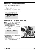
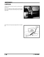
.006
″
(.15 mm)
INTAKE VALVE CLEARANCE
.006
″
(.15 mm)
EXHAUST VALVE CLEARANCE
2 Feeler Gauges
Summary of Contents for Sportsman 400
Page 6: ...SPORTSMAN 400 A01CH42AC GENERAL INFORMATION 1 4 MODEL COLOR IDENTIFICATION ...
Page 21: ...Newton Meter to Pound Foot and Pound Inch GENERAL INFORMATION 1 19 TORQUE CONVERSIONS ...
Page 22: ...Newton Meter to Pound Foot and Pound Inch GENERAL INFORMATION 1 20 TORQUE CONVERSIONS ...
Page 152: ...Forward FUEL SYSTEM CARBURETION 4 2 FUEL TANK ASSEMBLY ...
Page 366: ...ELECTRONIC SPEEDOMETER WIRING DIAGRAM ELECTRICAL 10 32 ...
Page 372: ...ELECTRICAL 10 38 NOTES ...
Page 379: ...ELECTRICAL 10 39 WIRING DIAGRAM 2001 SPORTSMAN 400 ...
Page 380: ...ELECTRICAL 10 40 WIRING DIAGRAM 2001 SPORTSMAN 500 EARLY ...
Page 381: ...ELECTRICAL 10 41 WIRING DIAGRAM 2001 SPORTSMAN 500 LATE ...


