FINAL DRIVE
7.16
AWD STRUT CASTING FRONT DRIVE AXLE SEAL REPLACEMENT
1.
Disassemble front hub. Refer to page 7.3.
2.
Remove the cotter pin and castle nut from the A-
arm ball joint. Separate A-arm from ball joint.
3.
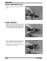
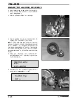
Remove the spindle and axle assembly from the
strut casting bearing by pulling the strut outward
as shown. Drive out the old seal, taking care not
to damage the tapered roller bearing. Install the
new seal until it bottoms against the shoulder in
the strut casting.
4.
Apply grease to the seal inner lip, reinstall the
spindle and axle assembly.
5.
Reinstall the A-arm to the ball joint. Torque to 25
ft. lbs. (35 Nm).
NOTE: If the cotter pin hole does not align at the
above torque, tighten slightly until the cotter pin hole
aligns and install the pin with open ends toward rear of
machine.
BEARING REPLACEMENT NOTE FOR FRONT DRIVE AXLE
AND FRONT HUB
NOTE: The front axle bearings have a larger I.D.
(1.0625
″
) than the hub bearings (1.000
″
). Be sure to
install the bearings with the larger I.D. in the strut
housing, and the bearings with the smaller I.D. in the
hub.
Pull
strut off
drive
shaft
Summary of Contents for Sportsman 400
Page 6: ...SPORTSMAN 400 A01CH42AC GENERAL INFORMATION 1 4 MODEL COLOR IDENTIFICATION ...
Page 21: ...Newton Meter to Pound Foot and Pound Inch GENERAL INFORMATION 1 19 TORQUE CONVERSIONS ...
Page 22: ...Newton Meter to Pound Foot and Pound Inch GENERAL INFORMATION 1 20 TORQUE CONVERSIONS ...
Page 152: ...Forward FUEL SYSTEM CARBURETION 4 2 FUEL TANK ASSEMBLY ...
Page 366: ...ELECTRONIC SPEEDOMETER WIRING DIAGRAM ELECTRICAL 10 32 ...
Page 372: ...ELECTRICAL 10 38 NOTES ...
Page 379: ...ELECTRICAL 10 39 WIRING DIAGRAM 2001 SPORTSMAN 400 ...
Page 380: ...ELECTRICAL 10 40 WIRING DIAGRAM 2001 SPORTSMAN 500 EARLY ...
Page 381: ...ELECTRICAL 10 41 WIRING DIAGRAM 2001 SPORTSMAN 500 LATE ...

