background image

Section 400-Programming

Introduction to DBS Programming

DBS-2.3/9.2-400

DBS Manual - Revised April 2000

  Intro-3

Before You Begin

This section describes preparations that should be completed 

before you start 

programming.

  If you are familiar with FF key programming for DBS 

systems, you may begin programming as soon as these preparations have 
been made.

If you are new to DBS programming, be sure to read 

“Understanding FF 

Key Programming”

 on page Intro-5 before you begin.

Preparations for Programming

Prior to programming the DBS system, make sure you have completed the 
following steps:

1.  Confirm that the DBS features meet customer requirements.  See 

Section 

700-Feature Operation 

for DBS feature descriptions.

2.  Confirm that you have the DBS hardware required for the end user.  See 

Section 300-Installation

 for details.

3. Use 

Forms and Tables (Section 450)

 to record the customer’s site data.  

Use the following guidelines when completing 

Forms and Tables:

•  Be sure to record 

all

 program entries. 

•  Leave the default values for equipment that is not connected.

•  Pay careful attention to program items that require a power-down to take 

effect.  Be sure to complete the necessary programming in these areas 
before you make the system operational. 

4.  To program a new DBS system, you must first initialize the software to 

default values (see 

“Initializing DBS Systems”

, next page).  If you are 

performing an upgrade and the system is using a CPC-B card, you must 
first perform the New Function Reset procedure (see 

“Upgrading CPC-B 

Software”

 on page Intro-5).

Once these steps are completed, use the site data in 

Forms and Tables

 to 

program the system.

Summary of Contents for DBS-2.3-400

Page 1: ...USA Section 400 Programming Digital Business System Doc Part No 7L0182AZDJ Applies to CPC AII B Version 9 2 and CPC EX Version 2 3 Version 2 3 9 2 Issued August 1 1995 Revised April 2000 ...

Page 2: ...ments and revisions PTSC cannot guarantee the accuracy of printed material after the date of publication nor can it accept responsibility for errors or omissions PTSC will update and revise this document as needed The software and hardware described in this document may be used or copied only in accordance with the terms of the license pertaining to said software or hardware 1995 by Panasonic Tele...

Page 3: ...Reset Intro 5 Understanding FF Key Programming Intro 6 Program Structure Intro 6 How to Enter the Programming Mode Intro 7 Example Programming Entry Intro 9 Default Program Settings Intro 9 Chapter 1 System Programming FF1 Date and Time Settings 1 3 Day Date Setting 1 3 Time Setting 1 5 General System Settings 1 6 Call Duration Display 1 6 SMDR Display Start Timer for CO Calls 1 7 Least Cost Routi...

Page 4: ...sition 1 32 Third Attendant Position 1 33 Fourth Attendant Position 1 34 Attendant Transfer Extension 1 35 Attendant Override 1 36 Attendant LED Alarm Indication 1 37 Extension BLF Delayed Ring 1 38 Analog Transfer Ring Pattern 1 39 Multiple DID DNIS 1 40 Page Duration 1 42 SLT DISA Ring Pattern 1 43 AEC Disconnect Signal Duration 1 44 DID DNIS to a Voice Mailbox 1 46 DID DNIS Answer Code 1 48 LCD...

Page 5: ...ent 1 75 Flexible Function Screen Text 1 80 Flexible Function Screen Default 1 81 Flexible Function Screens Default All 1 82 Caller ID Automatic DISA 1 83 Automatic DISA Callers 1 83 Door Phones 1 84 Door Phone Extensions 1 84 Door Phone Ring Assignments 1 86 Door Opener Access Code 1 88 Door Phone Tone Type 1 89 Door Phone Ring Timeout Timer 1 90 Door Phone Ring Pattern 1 91 Door Opener Relay Tim...

Page 6: ...rcom Calls 1 118 Extension Transfer Recall Timer for Intercom Calls 1 119 CO Delayed Ring Timer 1 120 Extension DSS BLF Delayed Ring Timer 1 122 Hunt Group No Answer Timer 1 124 Automatic Day Mode Start Time 1 125 Automatic Night 2 Mode Start Time 1 127 Programming and DISA Codes 1 129 Remote Programming ID Code 1 129 DISA Inbound Call ID Code 1 130 DISA Outbound Call ID Code 1 1 131 DISA Outbound...

Page 7: ...ms Recovery 1 176 Frame Loss Counter 1 177 Slip Counter 1 178 Red Alarm Counter 1 179 Loss of Signal Counter 1 180 Sync Loss Counter 1 181 Yellow Alarm Counter 1 182 Yellow Alarm Relay 1 183 Red Alarm Relay 1 184 Sync Loss Relay 1 185 Frame Loss Relay 1 186 AIS Relay 1 187 Relay Reset 1 188 T1 Trunk Type Emulation 1 189 DID DNIS 1 190 Outgoing Signaling Type 1 191 Incoming Signaling Type 1 192 Tru...

Page 8: ...Timer 2 15 DISA Start Time 2 16 DISA End Time 2 17 Trunk Circuit Type 2 18 DID Immediate or Wink Start 2 21 Wink Start Timer 2 22 Time Out for Dialed DID Digits 2 23 DID Interdigit Timeout 2 24 Trunk Port Class 2 25 Chapter 3 Extension Programming FF3 Extension Numbers 3 3 Terminal Type 3 5 EM 24 Port Assignment 3 7 Forced Least Cost Routing 3 8 Forced Account Codes 3 9 Extension Lockout Code 3 10...

Page 9: ...3 42 Station Port Class 3 43 SLT Hookflash 3 45 Extension Ring Pattern 3 46 Digital SLT Receiving Volume 3 48 Auto Set Relocation Code 3 49 Permanent Call Forward Type 3 51 Permanent Call Forward Extension 3 52 ML MCO Separation 3 53 VAU Hunting Priority 3 54 AEC Disconnect 3 55 VAU Port Assignment 3 56 Hot Dial Pad 3 57 Auto Redial on Extensions 3 58 Chapter 4 Ringing and Hunt Groups FF4 CO Day R...

Page 10: ...ssignments for Extensions 5 3 FF Key Assignments for DSS Consoles 5 8 Attendant Feature Package Key Assignments 5 10 Chapter 6 Name and Message Assignments FF6 General Notes 6 2 Extension Name 6 3 System Speed Dial Names 6 4 Personal Speed Dial Names 6 5 Absence Messages 6 6 Trunk Name Assignment 6 8 Hunt Group Name Assignment 6 9 Call Waiting OHVA Text Reply 6 10 DID DNIS Text Name Assignment 6 1...

Page 11: ...ypes 0 7 for Trunks 7 22 Area Code Table For TRS Types 3 6 Global Copy 7 23 Office Code Table For TRS Types 3 6 Global Copy 7 24 Area Office Code Table for TRS Types 3 6 Global Copy 7 25 Special Office Code Table For TRS Types 3 6 Global Copy 7 26 Chapter 8 Least Cost Routing FF8 An Overview of Least Cost Routing 8 2 LCR Area Codes 8 6 LCR Office Codes 8 7 Special LCR Area Codes 8 8 Special LCR Of...

Page 12: ...nitoring C 2 Analog Adapter C 2 MSG Message Key C 2 DSS 72 and EM 24 Key Arrangement C 2 FF Key Programming C 3 Speed Dial Enhancements C 3 Additional Serial Port C 3 T1 Networking Capability C 3 Modification to Toll Restriction Service C 3 Maximum Time Priority Route Tables C 3 SMDR Modifications C 4 ISDN Support C 4 Modification to T1 Signaling Types C 4 Installation Notes C 4 CPC EX Installatio...

Page 13: ...ection C 33 Remote CO Access C 33 SMDR Network Support C 34 Independent Node Attendant Assignment C 34 Settings Modified for Networking C 34 Extension Number Digits C 34 SMDR Printing Mode 1 Outbound and Inbound C 35 T1 Trunk Type C 35 Extension Numbers C 36 Forced LCR NRS C 36 Other Changes to Programming Addresses C 37 Enhanced Programming Addresses C 37 Modification to Toll Restriction Service ...

Page 14: ...ate Speaker Volumes for Internal vs CO calls D 12 Analog Adapter D 13 MSG Message Key D 15 DSS 72 Console Key Arrangement D 17 EM 24 Key Arrangement D 21 Modification to Toll Restriction Service D 23 TAPI Support D 26 Key Telephone Installation Notes D 27 Desi Strip Cover D 27 Key Telephone Wall Mounting Instructions D 27 Appendix E CPC AII B 9 0 Updates Appendix F CPC AII B 9 1 Updates Call Recor...

Page 15: ...ok Voice Announce OHVA via API J 2 Small LCD Softkey Support via API J 3 Call Record OHVA via API J 3 Appendix K CPC EX 2 3 Updates New Features K 1 Software Corrections K 2 16 Port Voice Mail Support via API K 3 Off Hook Voice Announce OHVA via API K 4 Small LCD Soft Key Support via API K 4 Call Record OHVA via API K 5 Special Features K 6 UNA Transfer K 6 UNA Call Reversion K 7 Forwarding to UNA...

Page 16: ... rotated desk stand C 6 Figure C 4 Handset guide insertion for wall mounting key telephone C 7 Figure C 5 44 Series Small Display Phone C 8 Figure C 6 44 Series Large Display Phone C 10 Figure C 7 DSS 72 Console VB 44320 key layout C 21 Figure C 8 DSS 72 1 Default Extension Numbers C 22 Figure C 9 EM 24 Unit VB 44310 keys C 24 Figure C 10 CPC EX Serial Port 2 C 29 Figure C 11 T1 Network Extension ...

Page 17: ...ld Recall Timer values 1 102 Table 1 17 Attendant Call Reversion Timer values 1 103 Table 1 18 Unsupervised Conference Timer values 1 104 Table 1 19 Automatic Pause Timer values 1 105 Table 1 20 CO Flash Timer values 1 106 Table 1 21 SLT Onhook Flash Timer values 1 108 Table 1 22 Inbound Ring Cycle Expansion Timer values 1 110 Table 1 23 Dial Pause Timer values 1 111 Table 1 24 PBX Flash Timer val...

Page 18: ... Table 2 2 Trunk Disconnect Detection Timer values 2 15 Table 2 3 Wink Start Timer settings 2 22 Table 2 4 DID Dialed Digit Timer values 2 23 Table 2 5 DID Interdigit Timer values 2 24 Table 2 6 Trunk Port Class circuit types 2 25 Table 3 1 Terminal Types 3 5 Table 3 2 Soft key menus during idle mode 3 23 Table 3 3 Soft key menus during intercom dial tone 3 25 Table 3 4 Soft key menus when calling...

Page 19: ...al programming 10 6 Table B 1 Terminal programming commands B 2 Table B 2 Codes for switching SMDR Bus Monitor modes B 3 Table C 1 44 Series Phones C 1 Table C 2 Small Display Phone Features C 8 Table C 3 Large Display Phone Features C 10 Table C 4 TRS Operator Access settings C 38 Table D 1 44 Series Phones D 3 Table D 2 Key to 44 Series Small Display Phone D 5 Table D 3 Key to 44 Series Large Di...

Page 20: ...Table of Contents Section 400 Programming xx DBS Manual revised April 2000 DBS 2 3 9 2 400 This page left blank intentionally ...

Page 21: ... FF7 Toll Restriction Chapter 8 FF8 Least Cost Routing Chapter 9 FF9 Program Copy Chapter 10 FF10 Speed Dial Numbers FF Key Programming FF key programming is accomplished by entering programming mode then punching in each program s address press the FF key then enter a string of numbers that are separated by the pound key The phone s LCD display will show prompts while you are punching in the stri...

Page 22: ...within them does not necessarily represent a logical progression for programming a particular feature or application For example some DID settings are in FF1 System while others are in FF2 Trunks FF3 Extensions and FF6 Names and Messages In Section 400 each program explanation includes related information about the feature or application it affects if any Also the forms in Section 450 of the DBS M...

Page 23: ... this manual The following table summarizes the topics contained in this introduction Topic Page Before You Begin Intro 3 Preparations for Programming Intro 3 Initializing DBS Systems RAMCLR Intro 4 Upgrading CPC B Software New Function Reset Intro 5 Understanding FF Key Programming Intro 6 Program Structure Intro 6 How to Enter the Programming Mode Intro 7 Example Programming Entry Intro 9 Defaul...

Page 24: ...Intro 2 DBS Manual Revised April 2000 DBS 2 3 9 2 400 ...

Page 25: ...Confirm that you have the DBS hardware required for the end user See Section 300 Installation for details 3 Use Forms and Tables Section 450 to record the customer s site data Use the following guidelines when completing Forms and Tables Be sure to record all program entries Leave the default values for equipment that is not connected Pay careful attention to program items that require a power dow...

Page 26: ...rsion 4 0 and upload them to the new version The new features introduced in CPC Versions 5 0 thru 6 1x as well as the Permanent Call Forwarding feature must be manually reprogrammed 1 Power off the DBS set power switch to OFF 2 Slide the CPC s SW1 switch to RAMCLR 3 Power on the DBS Wait until the bottom status LED on the CPC card stops flashing this takes less than a minute 4 Slide SW1 back to RA...

Page 27: ...rs that are extension based 1 Power off the DBS Remove the CPC B card 2 Replace the existing EPROMs 1 4 with new EPROMs 3 Re install the CPC B card then power the system back on 4 If upgrading to a new release perform New Function Reset as shown below 5 Power OFF the system wait at least 3 seconds then power it back ON IMPORTANT Perform New Function Reset if upgrading to a new whole number release...

Page 28: ...the Programming Mode next page press the desired FF key to start programming the entries addresses of the group The phone s LCD display will prompt you through the addresses Table 1 DBS program structure In the programming mode some of the phone keys can be used to store your settings and move forward or backward through the program addresses Figure 2 next page identifies these keys and what they ...

Page 29: ...two other phones can also be programmed as Third and Fourth Attendant phones Programming is also possible from other extensions see From a Non Attendant Port next page To enter the programming mode from any Attendant phone press ON OFF PROG desired FF key CONF Resets entry to default setting VOL Moves backward to the previous programming level FLASH Stores your entry and moves backward decrements ...

Page 30: ...t phone is used for programming you must enter the programming authorization code twice once to begin programming and once to exit programming Otherwise other non Attendant extensions cannot enter the programming mode Beginning with CPC A Version 3 3 and CPC B versions a non Attendant phone only has to enter the authorization code once to begin programming As soon as programming is complete any ot...

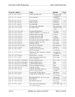
Page 31: ...ing table shows the default settings for all DBS program addresses Some of these addresses contain number ranges which are shown in parentheses These are the acceptable ranges for trunk numbers extension ports etc in a DBS 96 DBS 96 configuration with a CPC B card For the acceptable ranges in other configurations see Section 300 Installation Table 2 Default settings Program Address Topic Default P...

Page 32: ...F1 2 1 21 0 or 1 Voice Mail Busy Tone 0 Silence 1 26 FF1 2 1 22 0 6 Analog Transfer Ring Pattern CPC A 3 21 or higher 0 4 sec on 3 6 sec off 1 27 FF1 2 1 22 1 15 Attendant Overflow for Primary Attendant CPC B 1 0 only 8 maximum 8 stacked calls 1 28 FF1 2 1 23 0 or 1 Delayed Ring CPC AII B 0 Disabled 1 29 FF1 2 1 23 0 15 AEC Disconnect Signal Duration CPC A 3 3 or higher 0 No signal 1 30 FF1 2 1 24...

Page 33: ...rity 1 Even 1 54 FF1 2 2 3 1 4 Baud Rate 4 9600 bps 1 55 FF1 2 2 4 1 3 Stop Bit Length 1 1 bit 1 56 FF1 2 2 5 3 or 4 Data Length 4 8 bits 1 57 FF1 2 2 6 0 or 1 SMDR Printing Mode 1 Outbound and Inbound 1 Outbound and Inbound 1 58 FF1 2 2 7 0 or 1 SMDR Printing Mode 2 Long Distance and Local Calls 1 Long distance and local 1 59 FF1 2 2 8 0 or 1 SMDR Printing Mode 3 Header Title 0 No header titles 1...

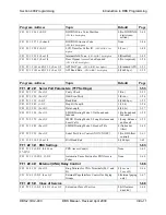
Page 34: ...99 Door Opener Access Code 9999 1 86 FF1 2 9 1 4 4 0 or 1 Door Phone Tone Type 0 Slow chime 1 87 FF1 2 9 1 4 5 0 15 Door Phone Ring Timeout Timer 3 20 sec 1 88 FF1 2 9 1 4 6 0 5 Door Phone Ring Pattern 1 4 sec between rings 1 89 FF1 2 9 1 4 7 0 5 Door Opener Relay Timer 1 Open for 4 sec 1 90 Program Address Topic Default Page FF1 3 System Timers 1 91 FF1 3 1 0000 2359 Automatic Night Mode Start Ti...

Page 35: ...ter 12 sec 1 118 FF1 3 27 0 15 Extension DSS BLF Delayed Ring Timer 2 After 12 sec 1 120 FF1 3 28 0 15 Hunt Group No Answer Timer 2 After 12 sec 1 122 FF1 3 29 HHMM Automatic Day Mode Start Time Not set 1 123 FF1 3 30 HHMM Automatic Night 2 Mode Start Time Not set 1 125 FF1 4 thru 7 Programming and DISA Codes 1 127 FF1 4 0000 9999 Remote Programming ID Code 9999 1 127 FF1 5 0000 9999 DISA Inbound ...

Page 36: ...re Mode 0 T1 continues to operate after error detected 1 162 FF1 8 4 4 5 1 6 0 or 1 Remote Loopback Reserved for future use 1 163 FF1 8 4 4 5 1 7 0 or 1 Yellow Alarm Send 1 Yes 1 164 FF1 8 4 4 5 1 8 0 or 1 Flash Key Operation 0 Release and reseize 1 165 FF1 8 4 4 5 2 1 0 5 Red Alarm Detection 2 8 1 166 FF1 8 4 4 5 2 2 0 15 Yellow Alarm Detection 1 50 ms 1 167 FF1 8 4 4 5 2 3 0 15 Yellow Alarm Reco...

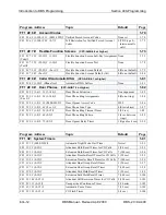
Page 37: ...FF1 8 4 7 0000 9999 10 69 or 100 699 DNIS Number Setting No assignment 1 197 FF1 8 5 0000 9999 10 69 or 100 699 0000 00 1111 11 DID Flexible Ringing Assignments 1100 or 111000 Ringingenabled Delayed ringing disabled 1 198 FF1 8 6 0000 9999 10 69 or 100 699 0000 00 1111 11 DNIS Flexible Ringing Assignments 1100 or 111000 Ringingenabled Delayed ringing disabled 1 198 FF1 8 7 1 2 1 4 1 8 0 or 1 T1 Tr...

Page 38: ...c 2 23 FF2 1 64 25 0 15 DID Interdigit Timeout 5 80 ms 2 24 FF2 1 64 26 4 8 Trunk Port Class Automatically set 2 25 Program Address Topic Default Page FF3 Extension Settings 3 1 FF3 1 144 1 10 69 or 100 699 Extension Numbers 10 100 Port 1 11 101 Port 2 etc 3 3 FF3 1 144 2 1 48 Terminal Type 4 34 button key phone 3 5 FF3 1 144 3 1 144 EM 24 Port Assignment No assignment 3 7 FF3 1 144 4 0 or 1 Force...

Page 39: ...r 0 5 names 3 39 FF3 1 72 34 0 or 1 VAU Port Assignment CPC A 3 3 or higher see page 3 56 FF3 1 144 35 0 8 Extension Class of Service Assignment CPC AII CPC B 3 1 or higher 0 Class 0 all features allowed 3 40 FF3 1 144 35 0000 9999 Inbound DID Dial Numbers CPC B 2 0 only No assignment 3 41 FF3 1 72 35 0 or 1 AEC Disconnect CPC A 3 3 or higher 0 Disabled 3 41 FF3 1 144 36 0 2 Ringback Tone From ML ...

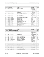
Page 40: ... 0 or higher 000 4 15 FF4 3 1 8 4 0 32 Hunt Group Transfer Timer CPC AII CPC B 2 0 or higher 2 2 sec 4 16 FF4 3 1 8 5 12 20 10 69 or 100 699 Hunt Group Members CPC AII CPC B 2 0 or higher No assignment 4 17 FF4 4 1 16 1 8 10 69 or 100 699 Call Coverage Group Members No assignment 4 18 FF4 5 1 73 145 1 64 0 or 1 CO Delayed Day Ring Assignments 0 No ring 4 20 FF4 5 79 86 or 151 158 1 64 0 or 1 CO De...

Page 41: ...har Trunk Name Assignment No assignment 6 8 FF6 6 1 8 CONF up to 10 char Hunt Group Name Assignment No assignment 6 9 FF6 7 1 5 CONF up to 15 char Call Waiting OHVA Text Reply No assignment 6 10 FF6 8 9 1 200 1 or 2 0000 9999 up to 6 char DID DNIS Text Name Assignment CPC B 5 0 or higher No assignment 6 11 Program Address Topic Default Page FF7 Toll Restrictions 7 1 FF7 1 1 0 or 1 International Ca...

Page 42: ... 1 4 000 999 0 or 1 Special Office Code Table For TRS Types 3 6 0 Allow for Sp A Cs 3 4 1 Deny for Sp A Cs 1 2 7 19 FF7 6 1 50 7 digitNo Special 7 Digit Table For TRS Types 2 6 No assignment 7 20 FF7 7 1 144 1 33 65 0 7 Day TRS Types 0 7 for Trunks 7 TRS type 7 all calls allowed 7 21 FF7 8 1 144 1 33 65 0 7 Night TRS Types 0 7 for Trunks 7 TRS type 7 all calls allowed 7 22 FF7 9 1 4 0 or 1 Area Co...

Page 43: ...8 Time Priority Route Tables No assignment 8 10 FF8 6 1 8 1 8 1 64 LCR Trunk Groups No assignment 8 12 FF8 7 1 8 up to 16 digits LCR Delete Tables No assignment 8 13 FF8 8 1 8 up to 16 digits LCR Add Tables No assignment 8 14 Program Address Topic Default Page FF9 Copy Program Settings 9 1 FF9 1 1 64 1 64 Trunk Copy Not set 9 3 FF9 2 1 144 1 144 Extension Copy Not set 9 4 FF9 3 1 144 1 144 FF Key ...

Page 44: ...Introduction to DBS Programming Section 400 Programming Intro 22 DBS Manual Revised April 2000 DBS 2 3 9 2 400 ...

Page 45: ...Settings 1 6 FF1 2 2 Serial Port Parameters TTY Settings 1 53 FF1 2 3 PBX Settings 1 63 FF1 2 4 External UNA Relay Control 1 66 FF1 2 5 Class of Service 1 68 FF1 2 6 Account Codes 1 70 FF1 2 7 Flexible Function Screens 1 73 FF1 2 8 Caller ID Automatic DISA 1 81 FF1 2 9 Door Phones CPC AII B 7 0 or higher 1 82 FF1 3 System Timers 1 91 FF1 4 thru 7 Programming and DISA Codes 1 127 FF1 8 1 and 2 New ...

Page 46: ...Page 1 2 DBS Manual Revised April 2000 DBS 2 3 9 2 400 ...
Page 47: ...r operation of peripheral equipment may also depend on correct date settings Programming Special Programming For Leap years starting February 2000 and beyond 2004 2008 etc the date must be programmed as described below with small DBS KSUs VB 42010 and VB 42020 The order of the procedure is very important The date must be programmed first then the day of the week Table 1 1 Date Day of Week Programm...

Page 48: ... 5 Six digit date Enter in the YYMMDD format Example 000229 is Feb 29 2000 6 7 8 9 10 11 One touch key No 1 Also called Personal Speed Dial keys lower left key 12 13 Number Day of week code Sunday Monday Tuesday Wednesday Thursday Friday Saturday 14 15 Day of the Week Programming Instructions YOU MUST USE EXT 10 ...

Page 49: ...ress FF1 1 2 HHMM Description This program sets the time in the DBS system clock The time appears on key phones that have LCDs The time is also recorded in SMDR call records Note Correct time settings are necessary for proper LCR Least Cost Routing operation Programming FF1 1 2 HHMM Time setting in 24 hour format for example 3 00 pm would be entered as 1500 ...

Page 50: ...ay Start Timer for CO Calls FF1 2 1 2 0 1 or 2 LCD Timer for Caller ID FF1 2 1 38 0 1 or 2 Notes No Interaction With SMDR Records This setting does not affect SMDR record generation Timing of Call Duration Display In CPC AII B Version 6 1 or higher using Caller ID the LCD Timer for Caller ID address FF1 2 1 38 determines the delay before call duration is displayed so that Caller ID information can...

Page 51: ...rts after the extension user dials the outgoing phone number This allows time for the CO to connect the call or the called party to answer before beginning the SMDR record Programming Related Programming Call Duration Display FF1 2 1 1 0 or 1 SMDR Communications Parameters FF1 2 2 1 thru 9 SMDR Report including the extension in FF3 ExtPort 14 0 or 1 Notes Caller ID Interaction In CPC AII B Version...

Page 52: ...the Call Forward Outside feature If LCR is activated the above address is set to 1 extensions set to Call Forward Outside must use trunk groups 1 6 trunk group 9 cannot be used See Section 700 Feature Operation for more information Required Hardware Setting Cut strap S1 on the CPC card to enable LCR See Section 300 Installation for instructions FCC Registration If strap S1 is cut a different FCC r...

Page 53: ...gramming To set a range of SSD numbers to override TRS settings enter the lowest SSD code in the range To reset to the default value By default SSD numbers do not override TRS types 2 6 To reset to default Related Programming TRS Settings all FF7 programs SSD Numbers FF10 1 SSD PhoneNo Notes SLT Audio Delay If Override Toll Restriction With SSD Numbers is executed on an SLT phone there is a 15 sec...

Page 54: ... higher The phone numbers associated with SSD codes 00 79 or 000 159 will always display during dialing regardless of the setting here If SSD Display Restriction is enabled set to 1 in this address the text assigned to the SSD code will display but the dialed digits will not Programming Related Programming Override TRS With SSD Numbers FF1 2 1 4 SSD SSD Name Display FF1 2 1 19 0 or 1 SSD Names FF6...

Page 55: ...ing a number If your DBS system is connected to a PBX set this address to 0 sending a flash may place the line to the PBX on hold Programming Related Programming CO Flash Timer FF1 3 13 0 15 PBX Flash Timer FF1 3 18 0 10 Trunk Port Type FF2 Trunk 10 1 or 2 Notes Flash Timing The CO Flash Timer FF1 3 11 determines the duration of a flash when REDIAL is pressed Ground Start Trunk Restriction The Fla...

Page 56: ...00 DBS 2 3 9 2 400 One Touch Dial Software Version All Versions Address FF1 2 1 7 0 or 1 Description The One Touch Dial feature enables users to dial an extension by pressing a single programmable key This feature is enabled regardless of the program setting One Touch Dial cannot be deactivated ...

Page 57: ...t Transfer Recall Timer for CO Calls FF1 3 4 0 12 Extension Transfer Recall Timer for CO Calls FF1 3 5 0 12 Attendant Transfer Recall Timer for Intercom Calls FF1 3 24 0 12 Extension Transfer Recall Timer for Intercom Calls FF1 3 25 0 12 Notes Call Transfer Limitation With CPC A In CPC A versions only trunk calls can be onhook transferred to other extensions In CPC AII and CPC B both trunk and int...

Page 58: ... the FF key for each trunk without placing the current trunk on hold an Attendant phone can press a DSS BLF key to automatically transfer a trunk call to an extension without pressing HOLD first In both cases the DBS will automatically place the current trunk call on System Hold anyone can pick up the call when the phone user presses the FF key or DSS BLF key If Key Bank Hold is disabled default s...

Page 59: ... call can be retrieved only on the extension where it was placed on hold System Hold default setting Any extension can pick up the call Programming Notes Applicable Phone Types This feature applies to both single line and digital telephones Number of Trunks That Can Be Held Without Key Appearances Phones that do not have a key appearance for trunk calls can only hold one trunk at a time VAU Intera...

Page 60: ...ss for both settings Table 1 2 SLT Hookflash Control Settings NOTE This address does not affect how the hookflash functions when the SLT user is listening to dial tone If SLT Flash Control Is Set to 0 If SLT Flash Control Is Set to 1 The user hookflashes to place a call on hold The user dials an extension number to transfer the call The extension is busy or does not answer The user hookflashes a s...

Page 61: ...amming Chapter 1 System Programming FF1 DBS 2 3 9 2 400 DBS Manual Revised April 2000 Page 1 17 Programming FF1 2 1 11 0 or 1 0 A second SLT hookflash results in dial tone 1 A second SLT hookflash retrieves a held call ...

Page 62: ...Programming Extension Numbers FF3 ExtPort 1 10 69 or 100 699 Notes Interaction With Larger Systems If more than 60 phones are installed in your system use 3 digit extension numbers Sites with fewer than 60 phones can use either 2 digit or 3 digit extension numbers Interaction With Voice Mail If your system uses Voice Mail use 3 digit numbers in order to match extensions with Voice Mail boxes Preca...

Page 63: ...ype FF3 ExtPort 2 Type Notes Alternate Attendant Phone Settings In Later DBS Versions In CPC B Version 2 0 and above and in all CPC AII versions you can program Second Third and Fourth Attendant phones instead of just one Alternate Attendant See FF1 2 1 24 thru 26 for more information Limitations on Assigning Attendant Phones The DBS system always recognizes the Primary Attendant location at exten...

Page 64: ...ver the extension loudspeaker By default a voice path is established when an Attendant dials an extension After the connection is established the Attendant can change from voice to ring or vice versa by dialing 1 Programming Related Programming Alert Tone for Voice Calls FF1 2 1 16 0 or 1 Notes Interaction With VAU If this address is set to Voice intercom calling and a VAU is used the VAU will not...

Page 65: ...ault a voice path is established when an extension dials another extension the called party can hear and talk to the caller without lifting the handset After the connection is established the caller can switch from voice to ring or vice versa by dialing 1 Programming Related Programming Alert Tone for Voice Calls FF1 2 1 16 0 or 1 Notes Interaction With VAU If this address is set to Voice intercom...

Page 66: ...ress to determine whether voice intercom calls are preceded by an initial alert splash tone By default the alert tone is enabled The alert tone if enabled will be sounded for 0 5 seconds before the caller s voice path is established Programming Related Programming Attendant Intercom Calling FF1 2 1 14 0 or 1 Extension Intercom Calling FF1 2 1 15 0 or 1 FF1 2 1 16 0 or 1 0 Alert tone is disabled 1 ...

Page 67: ...ttendant Override Busy Override and Offhook Voice Announce OHVA calls are preceded by an alert tone By default the alert tone is disabled This feature is governed by state law some states require the alert tone Programming Related Programming Busy Override Send FF3 ExtPort 9 0 or 1 Busy Override Receive FF3 ExtPort 10 0 or 1 Page Group Extensions FF3 ExtPort 18 thru 25 0 or 1 FF1 2 1 17 0 or 1 0 A...

Page 68: ...e dialed should not be changed Programming Related Programming Toll Restrictions FF7 Least Cost Routing FF8 Notes Interaction With TRS and LCR If 0 is selected above 1 is not required before a long distance call the system will look at the first three digits of the number dialed whether it s a 1 or not This would severely limit the capability of TRS and LCR which are based on 3 digit area codes If...

Page 69: ...an SSD menu is displayed When 5 names are displayed default setting the maximum length for each name is 16 characters When 10 names are displayed the maximum length for each name is 7 characters Programming Related Programming Override TRS with SSD Numbers FF1 2 1 4 SSD SSD Display Restriction FF1 2 1 5 0 or 1 SSD Menu display during call states FF3 ExtPort 26 thru 33 3 System Speed Dial Names FF6...

Page 70: ...Programming Related Programming Voice Mail Busy Tone FF1 2 1 21 0 or 1 Terminal Type FF3 ExtPort 2 21 28 31 38 or 41 48 Notes Third Party Voice Mail Systems Not Integrated With the DBS In these systems the API card is not required Set up Call Forward ID codes so that the DTMF codes will be sent to the appropriate Voice Mail box ON OFF PROG AUTO Ext up to 16 char HOLD See Section 700 Feature Operat...

Page 71: ...one Software Version All Versions Address FF1 2 1 21 0 or 1 Description This address determines what is sent to a voice mail port at the conclusion of a call either silence or a busy tone By default the DBS sends silence Programming Related Programming API AEC Slot Assignment FF1 2 1 20 2 18 FF1 2 1 21 0 or 1 0 Silence 1 Busy tone ...

Page 72: ...ern is 4 seconds on 3 6 seconds off This setting is typically used to assign specific ringing patterns for calls transferred to a modem or for SLTs that require distinctive ringing for transferred calls Programming Notes Analog Transfer Ring Pattern Setting for CPC AII and CPC B The Analog Transfer Ring Pattern for CPC AII all versions and CPC B Version 2 11 or higher is set in FF1 2 1 31 FF1 2 1 ...

Page 73: ...and Night Delayed Ring tables FF4 5 FF4 6 and FF4 9 2 The following types of calls can be stacked at the Primary Attendant Incoming trunk calls Hold recalls Transferred recalls Hunt group recalls Call reversions Programming Related Programming Attendant Hold Recall Timer FF1 3 2 0 12 Extension Hold Recall Timer FF1 3 3 0 12 Attendant Transfer Recall Timer FF1 3 4 0 12 Extension Transfer Recall Tim...

Page 74: ...on the system will send the call to another extension the first extension will cease ringing Programming Related Programming CO Delayed Ring Timer CPC AII and CPC B Ver 3 1 or higher FF1 3 26 0 15 CO Delayed Day Ring Assignments FF4 5 ExtPort Trunk CO Delayed Day Ring Assignments for Hunt Groups FF4 5 HuntGrp Trunk CO Delayed Night 1 Ring Assignments FF4 6 ExtPort Trunk CO Delayed Night 1 Ring Ass...

Page 75: ...lated Programming AEC Disconnect CPC A 3 3 or higher FF3 ExtPort 35 0 or 1 AEC Disconnect CPC AII B 5 0 or higher FF3 ExtPort 46 0 or 1 Notes AEC Disconnect Signal Duration for CPC B Versions For CPC B Version 5 0 and higher the AEC Disconnect Signal Duration is set in FF1 2 1 35 FF1 2 1 23 0 15 0 No disconnect signal 1 100 ms signal will be sent 2 200 ms signal will be sent 3 300 ms signal will b...

Page 76: ...n Number Digits FF1 2 1 12 0 or 1 Third Attendant Position FF1 2 1 25 11 69 or 101 699 Fourth Attendant Position FF1 2 1 26 11 69 or 101 699 Attendant Transfer Extension FF1 2 1 27 11 69 or 101 699 Extension Numbers assigning to ports FF3 ExtPort 1 ExtNo Notes Programming Restrictions A telephone must be plugged into the Second Attendant port before its extension number can be programmed or cleare...

Page 77: ...t position Related Programming Extension Number Digits FF1 2 1 12 0 or 1 Second Attendant Position FF1 2 1 24 11 69 or 101 699 Fourth Attendant Position FF1 2 1 26 11 69 or 101 699 Attendant Transfer Extension FF1 2 1 27 11 69 or 101 699 Extension Numbers assigning to ports FF3 ExtPort 1 ExtNo Notes Programming Restrictions A telephone must be plugged into the Third Attendant port before its exten...

Page 78: ...t position Related Programming Extension Number Digits FF1 2 1 12 0 or 1 Second Attendant Position FF1 2 1 24 11 69 or 101 699 Third Attendant Position FF1 2 1 25 11 69 or 101 699 Attendant Transfer Extension FF1 2 1 27 11 69 or 101 699 Extension Numbers assigning to ports FF3 ExtPort 1 ExtNo Notes Programming Restrictions A telephone must be plugged into the Fourth Attendant port before its exten...

Page 79: ...ll line appearances are busy on all Attendants Primary Second Third and Fourth calls will transfer to the extension assigned in this address Programming To assign an Attendant Transfer Extension To clear the Attendant Transfer Extension Notes Pilot Number Restriction The overflow position must be an installed extension it cannot be a hunt group pilot number FF1 2 1 27 11 69 or 101 699 Extension Nu...

Page 80: ...isable the Attendant Override feature which allows an Attendant phone to barge into a trunk or intercom call in progress on any extension even if the extension has been programmed to block barge ins By default Attendant Override is enabled When a barge in occurs all three parties can hear and talk to each other Programming Related Programming Alert Tone for Busy Override OHVA FF1 2 1 17 0 or 1 FF1...

Page 81: ...on an Attendant phone By default the Alarm feature can be assigned NOTE The Attendant Feature Package AFP was discontinued in CPC B Version 5 0 Programming Related Programming AFP Key Assignments FF5 149 152 1 72 FF12 4 Notes Installing AFP Installation of the AFP software requires the replacement of EPROM Chip 1 on the CPC B card with an AFP chip Make sure the new chip is installed in the proper ...

Page 82: ... disabled Delayed Ringing is a call forwarding feature for unanswered calls if an incoming call is not answered at one extension the system will send the call to another extension NOTE The extension to which the call is forwarded must have a DSS BLF key Programming Related Programming Extension Delayed Ring Table FF4 8 ExtPort ExtPort 0 or 1 Extension Delayed Ring Timer CPC B 2 0 or higher FF1 3 2...

Page 83: ... an SLT phone connected to an OPX Adapter or an SLT phone connected to an SLT A 4 port Adapter Programming Table 1 3 Analog Transfer Ring Patterns vary depending on analog connection Related Programming Analog Transfer Ring Pattern CPC A 3 21 or higher FF1 2 1 22 0 6 Terminal Type FF3 ExtPort 2 Type Extension Ring Pattern FF3 ExtPort 39 0 9 Address Setting Ring Pattern no of seconds on off for SLT...

Page 84: ...ed in the system Up to 500 DID numbers can be assigned to extension numbers in FF1 8 3 0000 9999 ExtNo DNIS stands for Dialed Number Identification Service DNIS is available only with the T1 Interface You can use DID and DNIS simultaneously in a T1 system Up to 500 DNIS numbers can be assigned to extension numbers in FF1 8 4 7 0000 9999 10 69 or 100 699 in addition to the 500 DID numbers allowed P...

Page 85: ...he wink is received the CO should wait at least 200 ms before sending the digits Trunk Requirement Individual trunks must be enabled for DID or DNIS see FF1 8 4 6 Trunk 2 Simultaneous Ringing If Multiple DID DNIS is enabled all extensions assigned the same DID DNIS number will ring for the incoming DID DNIS call If you later disable Multiple DID DNIS only the extension at the lowest numbered port ...

Page 86: ...33 0 or 1 Description This address determines whether the DBS system will automatically close the paging circuit 60 seconds after a page is initiated By default the paging circuit is left open indefinitely until the paging person closes the circuit by hanging up Programming FF1 2 1 33 0 or 1 0 The page circuit remains open indefinitely 1 The paging circuit remains open for 60 seconds before the sy...

Page 87: ...Address FF1 2 1 34 0 or 1 Description Use this address to specify a distinctive ring pattern for DISA calls on SLT phones or follow the Analog Transfer Ring Pattern setting By default the pattern is 1 second on 3 seconds off Programming Related Programming Analog Transfer Ring Pattern CPC AII and CPC B FF1 2 1 31 0 6 FF1 2 1 34 0 or 1 0 1 second on 3 seconds off 1 Same as the Analog Transfer Ring ...

Page 88: ...ty voice mail systems By default no disconnect signal is sent This address applies to CPC AII and CPC B The AEC Disconnect Signal Duration address for CPC A Version 3 3 or higher is FF1 2 1 23 0 15 The sending of the AEC disconnect signal can be enabled or disabled on individual extensions using FF3 ExtPort 46 Programming Table 1 4 AEC Disconnect Signal Duration values Setting Value 0 No disconnec...

Page 89: ...Section 400 Programming Chapter 1 System Programming FF1 DBS 2 3 9 2 400 DBS Manual Revised April 2000 Page 1 45 14 3 seconds 15 3 5 seconds Setting Value ...

Page 90: ...e mailbox plus the final DID DNIS digits if any specified in this address Programming Related Programming DID DNIS Answer Code FF1 2 1 37 NNNNNN DID DNIS enabling trunks for FF1 8 4 6 Trunk 2 0 2 Inbound DID Dial Numbers FF1 8 3 0000 9999 100 699 DNIS Number Setting FF1 8 4 7 0000 9999 10 69 or 100 699 Terminal Type FF3 ExtPort 2 Type Ringing Assignments trunks to extensions FF4 addresses Notes DI...

Page 91: ...y Voice Mail systems the Voice Mail can be connected through analog extension ports or OPX ports Call Forward ID Code for DID DNIS Calls To An Extension If a DID DNIS call is assigned to ring an extension and the extension is programmed to forward to Voice Mail only the Call Forward ID Code will be transmitted to Voice Mail the DID DNIS digits will not DID DNIS Data Transmission The DID DNIS digit...

Page 92: ...box Programming Related Programming DID DNIS to a Voice Mailbox FF1 2 1 36 0 1 or 2 DID DNIS enabling trunks for FF1 8 4 6 Trunk 2 0 2 Inbound DID Dial Numbers FF1 8 3 0000 9999 100 699 DNIS Number Setting FF1 8 4 7 0000 9999 10 69 or 100 699 Terminal Type FF3 ExtPort 2 Type Ringing Assignments trunks to extensions FF4 addresses Notes Assigning the DID DNIS Answer Code When Not In Programming Mode...

Page 93: ...d Party Voice Mail This feature can be used with Panasonic s Voice Mail system or with third party Voice Mail systems If the feature is used with third party Voice Mail systems the Voice Mail can be connected through analog extension ports or OPX ports Call Forward ID Code for DID DNIS Calls To An Extension If a DID DNIS call is assigned to ring an extension and the extension is programmed to forw...

Page 94: ...answered Programming Related Programming Call Duration Display FF1 2 1 1 0 or 1 SMDR Display Start Timer for CO Calls FF1 2 1 2 0 1 or 2 Notes SMDR Interaction The LCD Timer only affects the display of call duration The system begins the actual SMDR recording of the call according to the SMDR Start Timer address FF1 2 1 2 In order for call duration to be displayed the LCD Timer has to expire after...

Page 95: ... 0 or higher Address FF1 2 1 39 0 or 1 Description Use this address to enable or disable Internal Hold Tone which is a double beep heard every 7 seconds by a caller on hold Programming Notes MOH Override Internal Hold Tone if enabled will override any MOH Music On Hold sound source installed FF1 2 1 39 0 or 1 0 Disabled no Internal Hold Tone 1 Enabled Internal Hold Tone heard ...

Page 96: ...user answering a door phone call would unlock the door by pressing 3 NNNN where NNNN Access Code If set to 0 Not required the extension user answering the door phone call would simply press 3 Unlocking the Door Box From Another Extension The door can also be unlocked from any other extension not engaged in a door phone call If this address is set to 1 Required dial ON OFF 3 XXX NNNN on any extensi...

Page 97: ...0 or higher Address FF1 2 1 41 or 42 1 0 or 1 Description Use this address to configure the appropriate API port for TSAPI protocol Only one API port should be configured for TSAPI Programming Related Programming API Baud Rate FF1 2 1 41 or 42 2 0 or 1 FF1 2 1 41 or 42 1 0 or 1 API Port Number Port Type 0 Standard API protocol 1 TSAPI protocol 41 API Port 1 42 API Port 2 ...

Page 98: ...ress FF1 2 1 41 or 42 2 0 or 1 Description The baud rate for the TSAPI port can be set to either 9600 or 19200 bps Programming Related Programming API Port Type FF1 2 1 41 or 42 1 0 or 1 Notes Using Both API Ports If both API ports are being used both baud rates must be set to 9600 bps FF1 2 1 41 or 42 2 0 or 1 API Port Number Baud Rate 0 9600 bps 1 19200 bps 41 API Port 1 42 API Port 2 ...

Page 99: ...erial port CN6 By default parity checking is turned on If parity checking is activated select the parity count Even or Odd in FF1 2 2 2 Serial Port CN6 is normally used for SMDR Programming Related Programming Odd Even Parity FF1 2 2 2 0 or 1 Notes Checking Communications Parameters If you later change this address value be sure to check all Serial Port addresses FF1 2 2 1 thru 9 to make sure they...

Page 100: ...g for Serial Port CN6 was activated in FF1 2 2 1 this address Odd Even Parity determines whether the check is based on an even count or an odd count By default the parity count is even Programming Notes Checking Communications Parameters If you later change this address value be sure to check all Serial Port addresses FF1 2 2 1 thru 9 to make sure they are set properly FF1 2 2 2 0 or 1 0 Odd parit...

Page 101: ... to set data transmission speed baud rate between Serial Port CN6 and the peripheral equipment attached to it By default baud rate is set at 9600 bits per second Programming Notes Checking Communications Parameters If you later change this address value be sure to check all Serial Port addresses FF1 2 2 1 thru 9 to make sure they are set properly FF1 2 2 3 1 4 1 300 bps 2 1200 bps 3 4800 bps 4 960...

Page 102: ...escription This address sets the length of the stop bit parameter for transmitted data over Serial Port CN6 By default the stop bit length is set to 1 bit Programming Notes Checking Communications Parameters If you later change this address value be sure to check all Serial Port addresses FF1 2 2 1 thru 9 to make sure they are set properly FF1 2 2 4 1 3 1 1 bit 2 1 5 bits 3 2 bits ...

Page 103: ... 2 2 5 3 or 4 Description This address sets the length of the transmitted data string over Serial Port CN6 By default data length is set to 8 bits Programming Notes Checking Communications Parameters If you later change this address value be sure to check all Serial Port addresses FF1 2 2 1 thru 9 to make sure they are set properly FF1 2 2 5 3 or 4 3 7 bits 4 8 bits ...

Page 104: ... include both outbound and inbound calls or it can be limited to outbound calls only By default both outbound and inbound calls are recorded Programming Notes Bus Monitor Mode Interaction If the DBS is switched to Bus Monitor mode for troubleshooting the SMDR mode must be reactivated to resume SMDR output The SMDR mode can be reactivated from any Attendant phone by pressing ON OFF 93 ON OFF FF1 2 ...

Page 105: ...clude both local and long distance calls or it can be limited to long distance calls only By default both local and long distance calls are included Programming Notes Bus Monitor Mode Interaction If the DBS is switched to Bus Monitor mode for troubleshooting the SMDR mode must be reactivated to resume SMDR output The SMDR mode can be reactivated from any Attendant phone by pressing ON OFF 93 ON OF...

Page 106: ...DR report or the header title can be excluded from the report By default the header title is excluded The header title identifies the SMDR information in each column on the report Time Duration CO etc Programming Notes Bus Monitor Mode Interaction If the DBS is switched to Bus Monitor mode for troubleshooting the SMDR mode must be reactivated to resume SMDR output The SMDR mode can be reactivated ...

Page 107: ... the buffer empties XON XOFF should be deactivated default setting if a flow control mechanism is present elsewhere in the interface i e in the printer or RTS and CTS lines A flow control mechanism should always be present in order to prevent data from being lost during transmission Programming Notes DBS Buffer Size The size of the DBS buffer for SMDR is 8 kB This is the maximum amount of data tha...

Page 108: ...e RAI A and RAI B The following table shows the transmission rate of each card along with the SCC version with which it can be used Table 1 5 RAI Modem Card Compatibility Restrictions for Two Cabinet Systems Using Voice Mail In dual cabinet DBS systems that have a Voice Mail system connected to an analog extension port the RAI card s baud rate must be set to 300 bps See Technote 3 April 1991 for c...

Page 109: ...ill recognize the first dialed digits as the PBX Access Code separate from the outgoing phone number being dialed Otherwise the DBS will regard the Access Code as part of the outgoing phone number The DBS can use as many as 8 different PBX Access Codes Each Access Code can be one two or three digits long Programming To program a PBX Access Code To reset PBX Access Codes to default no codes created...

Page 110: ...ond or third digit The pause ensures that the PBX has time to connect to the CO before the DBS sends the PBX any digits If the pause is inadequate the DBS will send digits to the PBX too quickly causing the call attempt to fail Different pause sequences can be assigned to each PBX Access Code Programming To program an Automatic Pause Address No Dialed Digit 9 1 10 2 11 3 12 4 13 5 14 6 15 7 16 8 1...

Page 111: ... This sequence will insert a pause between the 9X and the rest of the dialed digits For example 91 PAUSE 404 555 5793 Inserting a pause after PBX Access Code 8 To insert a pause after the PBX access code 8 is dialed enter this address FF1 2 3 16 1 This sequence will insert a pause between the 8 and the rest of the dialed digits For example 8 PAUSE 404 555 5793 Related Programming Automatic Pause T...

Page 112: ...g pattern is 1 second on 3 seconds off This address controls the UNA relay terminals labeled M C and B on the DBS Connector Panel A bell or tone device can be attached to these relay terminals to transmit incoming ring over the loudspeaker See Section 300 Installation for more information about UNA Programming Related Programming CO Ring Assignments FF4 addresses CO Ring Cycle Detection Timer FF1 ...

Page 113: ...s initiated either zone paging or general paging occurs For external paging this is determined by the hardware connections to the DBS Connector Panel s CN2 terminal block see Section 300 Installation for instructions For internal paging this is determined by programming assigning extensions to page groups in FF3 ExtPort 18 25 Page Group 00 Pages to group 00 will be heard in all paging zones Addres...

Page 114: ...re numbered 1 8 An additional Class of Service 0 automatically enables all features and cannot be changed Classes of Service are assigned to extensions using FF3 ExtPort 35 0 8 Programming Table 1 5 Class of Service features Setting Value Feature Description 1 Dial Tone On Off 50 2 Head Handset Exchange 51 3 BGM On Off 53 4 Absence Message Set Reset 71 5 Call Forward Set Reset 72 6 Do Not Disturb ...

Page 115: ...the extension user may not be able to deactivate the feature For example if you reset Feature No 3 to 0 disabled while an extension has Background Music turned on the extension user will not be able to turn it off If this occurs re enable Feature No 3 for the Class of Service then turn Background Music off at the extension then disable Feature No 3 again Call Forward Outside 21 Feature Expansion B...

Page 116: ...ystem verification of the entered account code can be enabled or disabled on individual extensions see FF3 ExtPort 5 After verifying the entered account code the DBS will allow or disallow an outgoing call based on the TRS type assigned to the account code However if the system does not find a match for the account code in this address or if the TRS type restricts it the user cannot make the call ...

Page 117: ...0 Unverified Account Codes can only be used on a voluntary basis Forced Unverified is not available However beginning with Version 6 0 Forced Unverified Account Codes can be used See FF3 ExtPort 5 0 2 for more information TRS Interaction The default TRS type for Verified Forced Account Codes is 0 which generally allows intercom calling only Therefore if you assign an account code but do not assign...

Page 118: ...o enters the account code will be restricted by the TRS type assigned to the account code not the TRS type assigned to the extension Programming Related Programming Forced Account Codes FF3 ExtPort 5 0 1 or 2 Toll Restriction Settings FF7 addresses Notes TRS Interaction The default TRS type for Verified Forced Account Codes is 0 which generally allows intercom calling only Therefore if you assign ...

Page 119: ...screen is displayed One touch access to directories Pressing the soft key will display a directory of extension numbers Personal Speed Dial numbers or System Speed Dial numbers One touch initiation of a specific feature The soft keys can also execute any feature operation code except for Conference and Flash which already have their own fixed keys on the phone After the flexible function screens a...

Page 120: ...nks or feature codes For example Any Key can be used to store an account code or a Voice Mail password Attendant Park Hold 75 00 09 BGM Background Music On Off FF12 53 Busy Override PROG PROG 4 Call Forward Outside CPC AII B versions prior to 7 0 723 Feature Code FF1 2 7 1 25 39 1 10 xxxxxx Screen Number 25 Flex Func Screen 1 26 Flex Func Screen 2 27 Flex Func Screen 3 28 Flex Func Screen 4 29 Fle...

Page 121: ...gher FF12 520 Note The FF key LED will be off during Day mode red during Night mode and green during Night 2 mode Dial Tone Off FF12 50 DND Do Not Disturb 73 DP to DTMF Signal Conversion PROG PROG FF11 or PROG PROG FF12 DSS BLF Key internal calls PROG 10 69 or 100 699 Extension Directory 900002 Extension Lockout 74 Group Call Pickup 70 Headset FF12 51 Intercom Key FF12 8 Internal Dial Tone FF12 50...

Page 122: ...FF12 103 or 123 FF12 104 or 124 FF12 102 or 122 FF12 105 or 125 FF12 107 or 127 FF12 Talkback FF11 3 Tone Voice Calling PROG PROG 1 Transfer PROG PROG PROG Trunk Group Selection same as MCO or ML Keys 81 86 or 89 Trunk Queuing PROG PROG 2 Trunk Selection 01 64 UNA Pickup 78 Voice Mail One Touch Access CPC B Version 5 0 or higher PROG AUTO NNN XXX or AUTO SSD PSD VM Pilot Number Password optional P...

Page 123: ...Feature Codes The and phone keys are used as movement keys for scrolling through addresses while in programming mode Therefore when programming feature codes for soft keys FF11 and FF12 are used instead to represent and FF11 enters FF12 enters The phone will not display the symbol when you press FF11 or FF12 but it will register or as part of the feature code Initial Displays The 15 flexible funct...

Page 124: ...c characters on the digital keypad to assign the text in this address Programming Related Programming Flex Func Screen for Soft Keys FF1 2 7 1 Screen Key Code Flex Func Screen Default FF1 2 7 3 Screen 0 or 1 Flex Func Screens Default All FF1 2 7 4 0 or 1 Display Screens During Call States FF3 ExtPort 26 33 Screen Text up to 8 char FF1 2 7 2 25 39 1 10 xxxxxxxx Screen Number Soft Key Number 25 Flex...

Page 125: ...r Soft Keys FF1 2 7 1 Screen Key Code Flex Func Screen Text FF1 2 7 2 Screen Key Text Flex Func Screens Default All FF1 2 7 4 0 or 1 Display Screens During Call States FF3 ExtPort 26 33 Screen FF1 2 7 3 25 39 0 or 1 Screen Number 25 Flex Func Screen 1 26 Flex Func Screen 2 27 Flex Func Screen 3 28 Flex Func Screen 4 29 Flex Func Screen 5 30 Flex Func Screen 6 31 Flex Func Screen 7 32 Flex Func Scr...

Page 126: ...se this program to reinstate all 15 flexible function screens to the default value blank no features assigned to soft keys Programming Related Programming Flex Func Screen for Soft Keys FF1 2 7 1 Screen Key Code Flex Func Screen Text FF1 2 7 2 Screen Key Text Flex Func Screen Default FF1 2 7 3 Screen 0 or 1 Display Screens During Call States FF3 ExtPort 26 33 Screen FF1 2 7 4 0 or 1 0 Do not retur...

Page 127: ...lable only to another extension Note In order to use the Automatic DISA feature the DBS system must have a Caller ID package installed See Caller ID Installation and Operation Section 510 for more information Programming Notes Matching The Caller s Phone Number The caller s phone number entered in this address must exactly match the phone number received by Caller ID usually 10 digits Enabling DIS...

Page 128: ...C AII CPC B Version 7 0 and is controlled by the FF1 2 9 addresses below Door Phone Extensions Software Version CPC AII and CPC B Version 7 0 or higher Address FF1 2 9 DoorPhone 1 ExtPort Description Use this address to establish the extension ports that are connected to door phones Up to 4 door phones can be assigned one per extension port Programming Related Programming Door Phone Access Code Re...

Page 129: ...ardless of the extension s program settings It is not possible to Call Forward to a door phone It is not possible to Auto Redial to a door phone Door phone calls have the same priority as intercom extension calls All calls to a door phone are established as voice calls regardless of the extension s program settings The DTMF path is disabled during a door phone call When the extension user dials th...

Page 130: ...0000 9999 Door Phone Tone Type FF1 2 9 1 4 4 0 or 1 Door Phone Ring Timer FF1 2 9 1 4 5 0 15 Door Phone Ring Pattern FF1 2 9 1 4 6 0 5 Door Opener Relay Timer FF1 2 9 1 4 7 0 5 Notes Power Cycling Requirement In order for changes to this parameter to take effect the system must be turned off then back on Programming Restriction Programming an extension to ring for a door phone call must be perform...

Page 131: ...n the extension user dials the access code to unlock the door the visitor will not hear the DTMF digits Receiving a Door Phone Call When a visitor presses the door phone button an intercom call is generated automatically to the extension s assigned to ring for a door phone call If the extension is on hook the visitor will hear ringing tones The tones will stop when the extension user answers the d...

Page 132: ...1 4 7 0 5 Notes Unlocking the Door With the Access Code If Access Code NNNN is established in this address and Door Opener Access Code Required is enabled the extension user receiving the door phone call can press 3 NNNN while still engaged in the call to unlock the door Or from any other extension not engaged in a door phone call press ON OFF 3 XXX NNNN where XXX is the extension number assigned ...

Page 133: ...door phone button This applies to door phones connected to digital extension ports only not trunk ports Programming Related Programming Door Phone Ring Assignments FF1 2 9 DoorPhone 2 ExtPort 0 or 1 Door Phone Ring Timer FF1 2 9 DoorPhone 5 0 15 Door Phone Ring Pattern FF1 2 9 DoorPhone 6 0 5 Notes Reset Requirement If changing the Tone Type setting activate the change by unplugging the door phone...

Page 134: ... the call before this Timer is up the Timer will automatically reset and the extension will begin ringing again Programming Table 1 8 Door phone ring timer values Related Programming Door Phone Ring Pattern FF1 2 9 DoorPhone 6 0 5 Notes Reset Requirement If changing the Ring Timer setting activate the change by unplugging the door phone from its port and plugging it back in Setting Value Setting V...

Page 135: ... This address specifies the number of seconds between rings 4 seconds by default The ring itself has a fixed duration of approximately 3 seconds Programming Related Programming Door Phone Ring Timer FF1 2 9 DoorPhone 5 0 15 Notes Reset Requirement If changing the Ring Pattern setting activate the change by unplugging the door phone from its port and plugging it back in FF1 2 9 1 4 6 0 5 Door Phone...

Page 136: ...to enter the building 4 seconds by default This applies to door phones connected to digital extension ports only not trunk ports This Relay Timer begins immediately after an extension enters the appropriate codes 3 3 NNNN 3 XXX or 3 XXX NNNN to unlock the door Programming Related Programming Door Opener Access Code Required FF1 2 1 40 0 or 1 Door Opener Access Code FF1 2 9 1 4 3 0000 9999 FF1 2 9 ...

Page 137: ...ypes can be programmed to be used during Night mode see FF8 addresses NOTE Starting with Version 7 0 of the CPC AII and CPC B cards a second Night mode is also available see FF1 3 30 for more information Programming To set the Automatic Night Mode start time To clear the start time disable Automatic Night Mode Related Programming Time Setting FF1 1 2 HHMM Automatic Day Mode Start Time FF1 3 29 HHM...

Page 138: ... key to switch the mode again In CPC AII B versions prior to 7 0 if both Auto Day and Auto Night Mode Start Times are set the Attendant NIGHT key cannot be used to manually switch modes However it will work in Version 7 0 or higher or press 520 to toggle between Day Night and Night 2 modes SUGGESTION for versions prior to 7 0 Set only the Auto Night Mode Start Time so that the DBS will automatical...

Page 139: ...hone before it will recall 20 seconds by default Programming Table 1 9 Attendant Hold Recall Timer values for CO calls Related Programming Attendant Hold Recall Timer for Intercom Calls FF1 3 22 0 12 Setting Value 0 No recall 1 20 seconds 2 40 seconds 3 60 seconds 4 80 seconds 5 100 seconds 6 120 seconds 7 140 seconds 8 160 seconds 9 180 seconds 10 200 seconds 11 220 seconds 12 240 seconds FF1 3 2...

Page 140: ...sion Hold Recall Timer values for CO calls Related Programming Attendant Call Reversion Timer for CO Calls FF1 3 10 0 12 Notes Recall Treatment for CO Calls If a trunk recall is unanswered it will revert to the Attendant phone after ringing for the amount of time set in the Attendant Call Reversion Timer Setting Value 0 No recall 1 20 seconds 2 40 seconds 3 60 seconds 4 80 seconds 5 100 seconds 6 ...

Page 141: ... This timer determines how long a transferred trunk call will go unanswered before it recalls 20 seconds by default Programming Table 1 11 Attendant Transfer Recall Timer values for CO calls Related Programming Attendant Transfer Recall Timer for Intercom Calls FF1 3 24 0 12 Setting Value 0 No recall 1 20 seconds 2 40 seconds 3 60 seconds 4 80 seconds 5 100 seconds 6 120 seconds 7 140 seconds 8 16...

Page 142: ...calls 140 seconds by default Programming Table 1 12 Extension Transfer Recall Timer values for CO calls Related Programming Attendant Call Reversion Timer for CO Calls FF1 3 10 0 12 Notes Recall Treatment for CO Calls If a trunk recall is unanswered it will revert to the Attendant phone after ringing for the amount of time set in the Attendant Call Reversion Timer Setting Value 0 No recall 1 20 se...

Page 143: ...all to the Attendant if it is not answered This timer determines how long the call will go unanswered before it recalls 20 seconds by default Programming Table 1 13 Attendant Hunt Group Recall Timer values for CO calls Setting Value 0 No recall 1 20 seconds 2 40 seconds 3 60 seconds 4 80 seconds 5 100 seconds 6 120 seconds 7 140 seconds 8 160 seconds 9 180 seconds 10 200 seconds 11 220 seconds 12 ...

Page 144: ...extension if it is not answered This timer determines how long a transferred trunk call will go unanswered before it recalls 140 seconds by default Programming Table 1 14 Extension Hunt Group Recall Timer values for CO calls Setting Value 0 No recall 1 20 seconds 2 40 seconds 3 60 seconds 4 80 seconds 5 100 seconds 6 120 seconds 7 140 seconds 8 160 seconds 9 180 seconds 10 200 seconds 11 220 secon...

Page 145: ...sed by placing a call on hold then dialing 7500 7509 Anyone can pick up the call by dialing 7600 7609 This address determines how long a parked call will be held before it recalls 20 seconds by default Programming Table 1 15 Attendant Park Hold Recall Timer values Setting Value 0 No recall 1 20 seconds 2 40 seconds 3 60 seconds 4 80 seconds 5 100 seconds 6 120 seconds 7 140 seconds 8 160 seconds 9...

Page 146: ... by default Programming Table 1 16 Extension Park Hold Recall Timer values Related Programming Attendant Call Reversion Timer for CO Calls FF1 3 10 0 12 Notes Recall Treatment for CO Calls If a trunk recall is unanswered it will revert to the Attendant phone after ringing for the amount of time set in the Attendant Call Reversion Timer Setting Value 0 No recall 1 20 seconds 2 40 seconds 3 60 secon...

Page 147: ...unanswered on the holding extension Transfer recalls that are unanswered by the transferring extension Park recalls that are unanswered by the parking extension Programming Table 1 17 Attendant Call Reversion Timer values Related Programming Extension Hold Recall Timer for CO Calls FF1 3 3 0 12 Extension Transfer Recall Timer for CO Calls FF1 3 5 0 12 Extension Park Hold Recall Timer FF1 3 9 0 12 ...

Page 148: ...enced trunks This timer also determines how long outbound trunk calls made through DISA can last Programming Table 1 18 Unsupervised Conference Timer values Related Programming Unsupervised Trunk Conference FF2 Trunk 16 0 or 1 Unsupervised Conference FF3 ExtPort 13 0 or 1 Setting Value 0 Unlimited DBS will not disconnect the two conferenced trunks 1 5 minutes 2 10 minutes 3 15 minutes 4 20 minutes...

Page 149: ...es the length of each pause inserted by the REDIAL programming key 3 5 seconds by default Programming Table 1 19 Automatic Pause Timer values Related Programming Automatic Pause for PBX Line FF2 Trunk 13 0 or 1 PBX Access Codes FF1 2 3 1 8 0 999 or 0 99 Automatic Pause Position for PBX Access Codes FF1 2 3 9 18 1 3 Speed Dial Programming FF10 addresses Setting Value 0 No pause 1 5 seconds 2 1 seco...

Page 150: ...ceptions If the FLASH key is pressed and held down the flash signal will last as long as the key is pressed The flash generated by pressing REDIAL is always controlled by the CO Flash Timer regardless of how long REDIAL is held down Also if you are using a PBX or Centrex line the FLASH key will place the call on hold Programming Table 1 20 CO Flash Timer values Setting Value 0 No flash 1 2 seconds...

Page 151: ...ion The FLASH key function applies only to digital and digital single line telephones Trunk Type Restriction This timer only applies to loop start trunks FLASH and REDIAL Restriction FLASH and REDIAL features are not available with ground start trunks See Technote 13 March 1992 for further information SLT Flash Operation Single line telephones must press the hookswitch and dial 87 to activate this...

Page 152: ...ge Programming Table 1 21 SLT Onhook Flash Timer values Notes Power Cycling Requirement In order for changes to this program to take effect the system must be turned off then back on Address Setting Flash Treatment No Detection Valid Flash Disconnect 0 Less than 200 ms 200 to 500 ms Greater than 500 ms 1 Less than 200 ms 200 to 700 ms Greater than 700 ms 2 Less than 200 ms 200 to 1000 ms Greater t...

Page 153: ...n incoming trunk is 2 seconds on 4 seconds off this parameter should be set to at least 6 seconds to detect the full cycle If this timer is set too short the DBS will not recognize valid CO ring signals See Figure 1 2 below for an example of proper CO ring cycle detection timing for an incoming pattern of 2 seconds on 4 seconds off Figure 1 2 Example of a CO Ring Cycle and its Detection Timer Prog...

Page 154: ...ous page from the trunk To eliminate these short rings this timer can be used to expand initial ring bursts For example if the timer is set to 350 ms and the first ring burst only lasts 50 ms the first ring burst sent to the extension will be 350 ms If the first ring burst is over 350 ms the timer is ignored and the DBS emulates the initial CO ring Programming Table 1 22 Inbound Ring Cycle Expansi...

Page 155: ...ing dialed digits once a CO trunk is accessed The pause is used in speed dialing SSD and PSD and in Least Cost Routing LCR Programming Table 1 23 Dial Pause Timer values Setting Value 0 1 2 seconds 1 1 5 seconds 2 2 seconds 3 3 seconds 4 4 seconds 5 5 seconds 6 6 seconds 7 7 seconds 8 8 seconds 9 9 seconds 10 10 seconds 11 11 seconds 12 12 seconds 13 13 seconds 14 14 seconds 15 15 seconds FF1 3 17...

Page 156: ...ll last if the FLASH key is pressed then immediately released 8 seconds by default If the FLASH key is pressed and held down the flash signal will last as long as the key is pressed Programming Table 1 24 PBX Flash Timer values Related Programming Auto Flash Redial FF1 2 1 6 0 or 1 Trunk Port Type FF2 Trunk 10 1 or 2 Setting Value 0 No flash 1 2 seconds 2 3 seconds 3 4 seconds 4 5 seconds 5 6 seco...

Page 157: ...re it has its own address see Address column not available Control of this ring feature is not available in this CPC version Programming Table 1 26 Call Forward No Answer Timer values Address Ring Feature CPC A all CPC AII all CPC B prior to 3 1 CPC B 3 1 or higher FF1 3 19 Call Forward No Answer YES YES YES YES FF1 3 28 Hunt Group No Answer YES NO YES NO FF1 3 26 CO Delayed Ring not available NO ...

Page 158: ...side of the trunk In response the CO grounds the Tip side of the trunk When the DBS detects the Tip ground it will establish the connection the extension user will hear dial tone If the Tip ground is not received within the time set in this address the DBS will treat the trunk as unavailable the extension user will hear busy signal Programming Table 1 27 Outbound Ground Start Detection Timer value...

Page 159: ...BS trunk it signals the incoming call by grounding the Tip side of the trunk In most cases this timer should be set to 3 seconds or longer Otherwise the DBS may generate false ringing when Tip ground is not quickly removed at the end of a call Programming Table 1 28 Inbound Ground Start Detection Timer values Related Programming Outbound Ground Start Detection Timer FF1 3 20 1 8 Trunk Circuit Type...

Page 160: ...ain on hold at an Attendant phone before it recalls 20 seconds by default Programming Table 1 29 Attendant Hold Recall Timer values for intercom calls Related Programming Attendant Hold Recall Timer for CO Calls FF1 3 2 0 12 Setting Value 0 No recall 1 20 seconds 2 40 seconds 3 60 seconds 4 80 seconds 5 100 seconds 6 120 seconds 7 140 seconds 8 160 seconds 9 180 seconds 10 200 seconds 11 220 secon...

Page 161: ...ion phone before it recalls 140 seconds by default Programming Table 1 30 Extension Hold Recall Timer values for intercom calls Notes Recall Treatment for Intercom Calls Unanswered recalls for intercom calls will ring indefinitely at the extension Setting Value 0 No recall 1 20 seconds 2 40 seconds 3 60 seconds 4 80 seconds 5 100 seconds 6 120 seconds 7 140 seconds 8 160 seconds 9 180 seconds 10 2...

Page 162: ...dant Transfer Recall Timer values for intercom calls Related Programming Attendant Transfer Recall Timer for CO Calls FF1 3 4 0 12 Notes Call Forward Interaction If a call is transferred to an extension that has Call Forwarding turned on the call will follow the call forwarding path if the Call Forward No Answer Timer is less than the Recall Timer Setting Value 0 No recall 1 20 seconds 2 40 second...

Page 163: ... Extension Transfer Recall Timer values for intercom calls Related Programming Extension Transfer Recall Timer for CO Calls FF1 3 5 0 12 Notes Call Forward Interaction If a call is transferred to an extension that has Call Forwarding turned on the call will follow the call forwarding path if the Call Forward No Answer Timer is less than the Recall Timer Setting Value 0 No recall 1 20 seconds 2 40 ...

Page 164: ...ing at the first extension before it begins ringing at the second extension When the second extension begins ringing the first extension will stop ringing Programming Table 1 33 CO Delayed Ring Timer values Setting Value 0 After 4 seconds 1 After 8 seconds 2 After 12 seconds 3 After 16 seconds 4 After 20 seconds 5 After 24 seconds 6 After 28 seconds 7 After 32 seconds 8 After 34 seconds 9 After 36...

Page 165: ...nt Groups FF4 5 HuntGrp Trunk CO Delayed Night 1 Ring Assignments FF4 6 ExtPort Trunk CO Delayed Night 1 Ring Assignments for Hunt Groups FF4 6 HuntGrp Trunk CO Delayed Night 2 Ring Assignments FF4 9 2 ExtPort Trunk CO Delayed Night 2 Ring Assignments for Hunt Groups FF4 9 2 HuntGrp Trunk Notes CO Delayed Ring Control in Older CPC B Versions In CPC B versions prior to 3 1 CO delayed ringing is con...

Page 166: ...nsion before it begins ringing at the second extension When the second extension begins ringing the first extension will stop ringing Note The covering station needs a DSS BLF key Programming Table 1 34 Extension Delayed Ring Timer values Setting Value 0 After 4 seconds 1 After 8 seconds 2 After 12 seconds 3 After 16 seconds 4 After 20 seconds 5 After 24 seconds 6 After 28 seconds 7 After 32 secon...

Page 167: ...1 123 Related Programming Extension BLF Delayed Ring FF1 2 1 30 0 or 1 Extension Delayed Ring Table FF4 8 ExtPort ExtPort 0 or 1 Notes Extension Delayed Ring Control in Older CPC B Versions In CPC B versions prior to 3 1 extension delayed ringing is controlled by the Call Forward No Answer Timer FF1 3 19 0 15 ...

Page 168: ... default Programming Table 1 35 Hunt Group No Answer Timer values Notes Extension Delayed Ring Control in Older CPC B Versions In CPC B versions prior to 3 1 extension delayed ringing is controlled by the Call Forward No Answer Timer FF1 3 19 0 15 Setting Value 0 After 4 seconds 1 After 8 seconds 2 After 12 seconds 3 After 16 seconds 4 After 20 seconds 5 After 24 seconds 6 After 28 seconds 7 After...

Page 169: ... types can be programmed for use in each mode see FF8 addresses To set the automatic start time for Night mode use FF1 3 1 HHMM A second Night mode is also available in Version 7 0 or higher of CPC AII or CPC B see FF1 3 30 HHMM Programming To set the Automatic Day Mode Start Time Enter the time using the 24 hour format The following example sets the time to 8 30 a m To clear the Start Time disabl...

Page 170: ...e mode is automatically activated before using the NIGHT key to switch the mode again In CPC AII B versions prior to 7 0 if both Auto Day and Auto Night Mode Start Times are set the Attendant NIGHT key cannot be used to manually switch modes However it will work in Version 7 0 or higher or press 520 to toggle between Day Night and Night 2 modes SUGGESTION for versions prior to 7 0 Set only the Aut...

Page 171: ...r Night mode see FF4 addresses And different TRS types can be programmed for use in each mode see FF8 addresses To set the automatic start time for Night mode use FF1 3 1 HHMM To set the Automatic Day Mode Start Time use FF1 3 29 HHMM Programming To set the Automatic Night 2 Mode Start Time To clear the start time disable Night 2 Mode Related Programming Time Setting FF1 1 2 HHMM Automatic Day Mod...

Page 172: ...GHT key to switch the mode again In CPC AII B versions prior to 7 0 if both Auto Day and Auto Night Mode Start Times are set the Attendant NIGHT key cannot be used to manually switch modes However it will work in Version 7 0 or higher or press 520 to toggle between Day Night and Night 2 modes SUGGESTION for versions prior to 7 0 Set only the Auto Night Mode Start Time so that the DBS will automati...

Page 173: ...cal PC connected directly to the SMDR port CN6 You can enter the remote programming mode through any of these three methods By dialing into the system through a direct DISA trunk By dialing into the system through a regular CO trunk then requesting the operator to enter the Remote Programming ID Code By using a local PC and communications package to connect directly to the DBS serial port For more...

Page 174: ...one immediately without entering an ID code If you define a DISA Inbound Call ID Code in this address callers dialing in on the DISA trunk will receive a fast busy tone The caller must then dial the DISA Inbound Call ID Code to receive the intercom dial tone Programming To set the DISA ID Code To clear the DISA ID Code Related Programming DISA Outbound Call ID Code 1 FF1 6 1 0000 9999 DISA Outboun...

Page 175: ...uto Answer FF2 Trunk 11 0 or 1 DISA Inbound Call ID Code FF1 5 0000 9999 DISA Outbound Call ID Code 2 FF1 6 2 0000 9999 DISA Start Time FF2 Trunk 19 HHMM DISA End Time FF2 Trunk 20 HHMM Notes DISA Limitations 1 A 16 second timer is set between the dialing of the DISA Outbound ID Code If a time out results the DISA call is treated as a normal call 2 The DBS supports up to two valid 4 digit DISA Out...

Page 176: ...A Auto Answer FF2 Trunk 11 0 or 1 DISA Inbound Call ID Code FF1 5 0000 9999 DISA Outbound Call ID Code 1 FF1 6 1 0000 9999 DISA Start Time FF2 Trunk 19 HHMM DISA End Time FF2 Trunk 20 HHMM Notes DISA Limitations 1 A 16 second timer is set between the dialing of the DISA Outbound ID Code If a time out results the DISA call is treated as a normal call 2 The DBS supports up to two valid 4 digit DISA ...

Page 177: ...rom a non Attendant phone to enter the programming mode 9999 by default Non Attendant extensions enter the programming mode by dialing 98 and then the ID Code entered in this address Programming To assign the ID Code for system programming To reset the ID Code to default 9999 Notes Entering the Programming Mode Only one extension can be in programming mode at a particular time FF1 7 0000 9999 4 Di...

Page 178: ...rs and adds new programs but retains all current DBS program settings Exception If you are upgrading from a CPC B version prior to 3 1 New Function Reset will clear existing DID numbers which are extension based see FF3 ExtPort 35 Beginning with Version 3 1 DID numbers are stored in the Inbound DID Numbers table see FF1 8 3 address New Function Reset will erase extension based DID numbers but it w...

Page 179: ...entries taken up is equal to the number of DID numbers assigned to the extension Programming Related Programming Multiple DID DNIS FF1 2 1 32 0 or 1 DID DNIS enabling trunks for FF1 8 4 6 Trunk 2 0 2 DID Flexible Ringing Assignments FF1 8 5 DIDNo ExtNo 0000 00 1111 11 DID Immediate or Wink Start FF2 Trunk 22 0 or 1 Wink Start Timer FF2 Trunk 23 0 15 Time Out for Dialed DID Digits FF2 Trunk 24 0 15...

Page 180: ... card requires an external 48V power supply Also SCC B Card Version 1 2 or higher is required See Section 300 Installation for cabling instructions Dial Pulse Requirement The DID trunk card requires dial pulse dialing Digit Length Requirement The DBS only supports 4 digit DID numbers DID Ring Control Ringing for the DID number at the assigned extension s is controlled by the DID Flexible Ringing A...

Page 181: ...iguration for T1 installation Notes Power Cycling Requirement For changes to this parameter to take effect the system must be turned off then back on Minimum T1 Programming The following table see next page lists the programs that need to be set in order to make T1 operational Default settings appear in bold In most cases you do not have to change the defaults for any remaining T1 programs Setting...

Page 182: ... DBS 72 2 DBS 96 3 DBS 40 DBS 40 T1 must be in slave cabinet 4 DBS 72 DBS 40 T1 is not supported 5 DBS 72 DBS 72 T1 must be in slave cabinet 6 DBS 96 DBS 40 7 DBS 96 DBS 72 8 DBS 96 DBS 96 Address FF1 8 4 1 2 1 3 for Sync Source 1 FF1 8 4 1 3 0 3 for Sync Source 2 FF1 8 4 1 4 0 3 for Sync Source 3 Description Assign the sync sources The Sync Card installed on the CPC B provides a method of synchro...

Page 183: ...ng default for Sync Source 1 Examples In most cases the sync sources should be set as follows for these system configurations T1 in a Single Cabinet or T1 in a Master Cabinet Sync Source 1 1 T1 of the master cabinet Sync Source 2 3 Free run Sync Source 3 0 None T1 in a Slave Cabinet Sync Source 1 2 T1 of the slave cabinet Sync Source 2 3 Free run Sync Source 3 0 None T1s in the Master and Slave Ca...

Page 184: ...g format ordered from the CO In most cases SF SuperFrame also known as D4 is used SF consists of 12 frames with each frame including 192 information bits ESF Extended SuperFrame can also be selected ESF consists of 24 frames and supports monitoring and mainte nance capabilities not available in the SF format For changes to this parameter to take effect the system must be powered down then powered ...

Page 185: ...g trunk ports on the TRK card are opened for analog usage in the T1 Trunk Closure address see FF1 8 7 in this DBS Manual For changes to this parameter to take effect the system must be powered down then powered back up Options 0 Loop Start 1 Ground Start 2 Analog DID 3 T1 4 Caller ID loop start available only with CPC B Version 6 1 or higher Address FF1 8 4 6 1 64 1 0 3 Description Specify the typ...

Page 186: ...tch the signaling ordered from the CO For changes to this parameter to take effect the system must be powered down then powered back up Options 0 Immediate Start 1 Wink Start 2 Dial Tone Start Address FF1 8 4 6 1 64 4 0 or 1 Description Specify the incoming signaling type used by the T1 Be sure to match the signaling ordered from the CO For changes to this parameter to take effect the system must ...

Page 187: ...nter is exceeded within a 24 hour period See FF1 8 4 4 5 3 2 0 9000 for instructions on setting the Slip Counter Typically Sync Source 1 is T1 of the master cabinet See Notes below for a list of typical sync source settings for single and double cabinet systems Programming Notes Typical Sync Settings In most cases sync sources should be set as follows for these configurations T1 in a Single Cabine...

Page 188: ...Manual Revised April 2000 DBS 2 3 9 2 400 Restriction on Duplicate Sync Settings Free run is the only setting that can be entered for more than one sync source Power Cycling Requirement For changes to this parameter to take effect the system must be turned off then back on ...

Page 189: ...d sync source set to 3 Free run Systems with two T1s normally have the second sync source set to 2 T1 of the slave cabinet NOTE One of the three sync sources should be set to 3 Free run so that the T1 can provide its own clocking if the network clock fails See the Sync Source 1 address for an introduction to T1 clocking and a list of typical sync source settings in single cabinet and double cabine...

Page 190: ...h two T1s normally have the third sync source set to 3 Free run NOTE One of the three sync sources should be set to 3 Free run so that the T1 can provide its own clocking if the network clock fails See the Sync Source 1 address for an introduction to T1 clocking and a list of typical sync source settings in single cabinet and double cabinet systems Programming Notes Restriction on Duplicate Sync S...

Page 191: ...locking sync source fails the system will switch to the second source and then will attempt to return to the first source once an hour for the number of times set in Network Re Sync Timer Likewise if the system switches to the third source after the first and second sources fail the Network Re Sync Timer determines how many times the system will attempt to return to the original clocking source Pr...

Page 192: ...nect Timer FF2 Trunk 18 0 15 determines how long the system waits to receive a disconnect signal from the CO Programming Table 1 38 T1 Disconnect Timer values Notes Power Cycling Requirement For changes to this parameter to take effect the system must be turned off then back on Setting Value 0 150 ms 1 200 ms 2 250 ms 3 300 ms 4 400 ms 5 500 ms 6 1000 ms 7 1500 ms 8 2000 ms 9 2500 ms 10 3000 ms 11...

Page 193: ... to make sure the previous call is properly disconnected This means the channel cannot be used for another call until the Guard Timer has expired Programming Table 1 39 T1 Guard Timer values Notes Power Cycling Requirement For changes to this parameter to take effect the system must be turned off then back on Setting Value 0 200 ms 1 300 ms 2 400 ms 3 500 ms 4 800 ms 5 1000 ms 6 1200 ms 7 1400 ms ...

Page 194: ...will abandon the call even if the CO has not acknowledged the disconnect This allows the DBS to disconnect idle T1 trunks if the CO is not signaling properly Programming Table 1 40 Release Acknowledge Timer values Setting Value 0 1 second 1 2 seconds 2 5 seconds 3 10 seconds 4 20 seconds 5 30 seconds 6 60 seconds 7 90 seconds 8 120 seconds 9 240 seconds 10 480 seconds 11 960 seconds 12 1 080 secon...

Page 195: ... higher Address FF1 8 4 2 5 0 8 Description Determines how long the system waits before outpulsing dialed digits to the network 500 ms by default Programming Table 1 41 Outpulse Delay Timer values Setting Value 0 100 ms 1 300 ms 2 500 ms 3 700 ms 4 1000 ms 5 1200 ms 6 1500 ms 7 1700 ms 8 2000 ms FF1 8 4 2 5 0 8 Outpulse Delay Timer setting Default 2 500 ms see table below ...

Page 196: ...l tone to the extension This timer determines how long the DBS waits for a wink signal once an extension user goes off hook 5500 ms by default If the DBS does not receive a wink signal before the timer expires the DBS disconnects the T1 channel and returns busy tone to the user Programming Table 1 42 Wink Timeout Timer values Setting Value 0 150 ms 1 250 ms 2 500 ms 3 750 ms 4 1000 ms 5 1250 ms 6 ...

Page 197: ...ng the DBS waits before recognizing the seizure as an incoming call 90 ms by default The purpose of this timer is to prevent false incoming ringing This parameter only applies when E M signaling is used Programming Table 1 43 Incoming Detection Timer values Setting Value 0 20 ms 1 30 ms 2 40 ms 3 50 ms 4 60 ms 5 70 ms 6 80 ms 7 90 ms 8 100 ms 9 110 ms 10 120 ms 11 130 ms 12 140 ms 13 150 ms 14 160...

Page 198: ...the T1 answer supervision is provided to determine if the call is actually answered This timer determines how long the offhook signal from the called party must last before the DBS treats the offhook signal as an answer Programming Table 1 44 Answer Supervision Timer values Setting Value 0 50 ms 1 100 ms 2 200 ms 3 600 ms 4 1000 ms 5 2000 ms 6 3000 ms 7 4000 ms 8 10 000 ms FF1 8 4 2 8 0 8 Answer S...

Page 199: ...ne Use this address to prevent glare when immediate start signaling is used This timer determines how long the DBS will search for an incoming call on a trunk channel before connecting a DBS extension user to it 60 ms by default The timer begins when the extension goes off hook Programming Table 1 45 Immediate Glare Timer values Setting Value 0 The DBS does not check for glare 1 20 ms 2 40 ms 3 60...

Page 200: ...line Use this address to prevent glare from occurring when wink start signaling is used This timer determines how long the DBS will search for an incoming call on a trunk channel before connecting a DBS extension user to it 60 ms by default The timer begins when a wink is received Programming Table 1 46 Wink Glare Timer values Setting Value 0 The DBS does not check for glare 1 20 ms 2 40 ms 3 60 m...

Page 201: ...In most cases the default pad settings do not need to be changed If the volume level of a connection is unsatisfactory include the Receiving and Sending circuit types in this program and then adjust the volume by assigning a new pad number Programming Table 1 47 Digital Pad Settings circuit types Circuit Type Setting Value Notes 1 K Tel 2 SLT 3 Data Reserved for future use 4 Analog CO Trunk 5 T1 m...

Page 202: ...ExtPort 37 1 2 or 7 8 Pad No dB Level Pad No dB Level 0 0 dB 16 2 dB 1 2 dB 17 4 dB 2 4 dB 18 6 dB 3 6 dB 19 8 dB 4 8 dB 20 10 dB 5 10 dB 21 12 dB 6 12 dB 22 14 dB 7 14 dB 23 16 dB 8 16 dB 24 18 dB 9 18 dB 26 20 dB 10 20 dB 27 22 dB 11 22 dB 28 24 dB 12 24 dB 29 26 dB 13 26 dB 30 28 dB 14 28 dB 15 30 dB From To Setting Value T1 master T1 slave K Tel K Tel 16 16 2 dB 2 dB T1 master T1 slave SLT SLT...

Page 203: ...vels the pad level for connections from the master T1 to all SLTs can be changed By default the pad level for connections from the master T1 to all SLTs is 16 or 2 dB To raise the volume by 2 dB change the pad value to 0 or 0 dB by programming the following FF1 8 4 3 2 5 0 where 2 is the circuit type for SLTs 5 is the circuit type for T1 in the master cabinet and 0 is the pad number for 0 dB loss ...

Page 204: ...in the same cabinet Each T1 channel uses up one trunk port on the analog trunk card Programming Related Programming Number of T1 Channels FF1 8 4 4 or 5 1 2 0 24 T1 Trunk Closure FF1 8 7 1 or 2 1 4 1 8 0 or 1 Trunk Circuit Type FF2 Trunk 21 0 3 Notes Power Cycling Requirement For changes to this parameter to take effect the system must be turned off then back on CPC B Versions Beginning With 6 03 ...

Page 205: ... Number of T1 Channels must be in increments of 8 This is because the entire analog trunk card all 8 trunk ports on the same card must be dedicated to T1 even if only some of the ports are used for T1 channels In other words the remaining unused ports on the card are not available for use as analog trunks In CPC B Version 5 0 and above those remaining ports can be used as analog trunks Make sure t...

Page 206: ...gramming Page 1 162 DBS Manual Revised April 2000 DBS 2 3 9 2 400 Closing Analog Trunk Ports for T1 Usage In CPC B Versions 5 0 to 6 02 make sure the trunk ports reserved for T1 are closed from loop start usage in the T1 Trunk Closure address FF1 8 7 ...

Page 207: ... SF consists of 12 frames with each frame including 192 information bits and 1 framing bit The ESF consists of 24 frames double the length of the SF format ESF also supports monitoring and maintenance capabilities that are not available with the SF format Programming Notes Central Office Requirement The framing format must match what is ordered from the CO Power Cycling Requirement For changes to ...

Page 208: ...ormat used by the T1 Either B8ZS binary 8 zeros suppression or AMI Alternate Mark Inversion can be selected In most cases and by default AMI is used Programming Notes Central Office Requirement The framing format must match what is ordered from the CO Power Cycling Requirement For changes to this parameter to take effect the system must be turned off then back on FF1 8 4 4 or 5 1 4 0 or 1 4 Master...

Page 209: ... or 1 Description Determines the way the system responds to alarms By default the system will continue to operate even if errors are detected Programming Notes Power Cycling Requirement For changes to this parameter to take effect the system must be turned off then back on FF1 8 4 4 or 5 1 5 0 or 1 4 Master Cabinet 5 Slave Cabinet 0 Mode 1 the T1 continues to operate even if errors are detected 1 ...

Page 210: ...ming Page 1 166 DBS Manual Revised April 2000 DBS 2 3 9 2 400 Remote Loopback Software Version CPC B Version 4 0 or higher Address Master Cabinet FF1 8 4 4 1 6 0 or 1 Slave Cabinet FF1 8 4 5 1 6 0 or 1 Description This address is reserved for future use ...

Page 211: ...t to the distant end of the T1 link to indicate that a red alarm has occurred If a red alarm occurs at the CO the CO sends a yellow alarm to the DBS If a red alarm occurs at the DBS the DBS sends a yellow alarm to the CO Programming Related Programming Yellow Alarm Detection FF1 8 4 4 or 5 2 2 0 15 Yellow Alarm Recovery FF1 8 4 4 or 5 2 3 0 15 Yellow Alarm Counter FF1 8 4 4 or 5 3 6 0 15 Yellow Al...

Page 212: ...ftware Version CPC B Version 4 0 or higher Address Master Cabinet FF1 8 4 4 1 8 0 or 1 Slave Cabinet FF1 8 4 5 1 8 0 or 1 Description In the current version of DBS T1 a switchhook flash releases and reseizes the T1 line Programming FF1 8 4 4 or 5 1 8 0 or 1 4 Master Cabinet 5 Slave Cabinet 0 Release and reseize 1 Reserved for future use ...

Page 213: ...or this parameter is determined by network specifications It should not be changed If a red alarm occurs the CFA LED on the T1 card lights Also if the Red Alarm Relay FF1 8 4 4 5 4 2 is enabled the alarm relay on the T1 MDF card closes Programming Related Programming Red Alarm Counter FF1 8 4 4 or 5 3 3 0 9000 Red Alarm Relay FF1 8 4 4 or 5 4 2 0 or 1 Red Alarm FF Key FF5 ExtPort Key CONF 103 or 1...

Page 214: ...ystem detects a yellow alarm When a yellow alarm occurs the YEL LED on the T1 card lights Also if the Yellow Alarm Relay FF1 8 4 4 5 4 1 is enabled the alarm relay on the T1 MDF card closes Programming Table 1 50 Yellow Alarm Detection timer values Setting Value 0 0 ms 1 50 ms 2 100 ms 3 150 ms 4 200 ms 5 250 ms 6 300 ms 7 350 ms 8 400 ms 9 450 ms 10 500 ms 11 550 ms 12 600 ms 13 650 ms 14 700 ms ...

Page 215: ...ated Programming Yellow Alarm Send FF1 8 4 4 or 5 1 7 0 or 1 Yellow Alarm Recovery FF1 8 4 4 or 5 2 3 0 15 Yellow Alarm Counter FF1 8 4 4 or 5 3 6 0 9000 Yellow Alarm Relay FF1 8 4 4 or 5 4 1 0 or 1 Notes Power Cycling Requirement For changes to this parameter to take effect the system must be turned off then back on ...

Page 216: ...3 0 15 Description Determines how long the DBS tries to recover from a yellow alarm before it re syncs the T1 trunk Programming Table 1 51 Yellow Alarm Recovery timer values Setting Value 0 0 ms 1 10 ms 2 20 ms 3 30 ms 4 40 ms 5 50 ms 6 60 ms 7 70 ms 8 80 ms 9 90 ms 10 110 ms 11 120 ms 12 130 ms 13 140 ms 14 150 ms 15 160 ms FF1 8 4 4 or 5 2 3 0 15 4 Master Cabinet Yellow Alarm Recovery timer sett...

Page 217: ...ated Programming Yellow Alarm Send FF1 8 4 4 or 5 1 7 0 or 1 Yellow Alarm Detection FF1 8 4 4 or 5 2 2 0 15 Yellow Alarm Counter FF1 8 4 4 or 5 3 6 0 9000 Yellow Alarm Relay FF1 8 4 4 or 5 4 1 0 or 1 Notes Power Cycling Requirement For changes to this parameter to take effect the system must be turned off then back on ...

Page 218: ...s an alarm If an OOF Sync Loss or AIS alarm occurs a corresponding LED on the T1 card lights Sync Loss alarms light the SLIP LED The alarm relay on the T1 MDF card will also close if the corresponding relay parameter is enabled Programming Table 1 52 Other Alarms Detection timer values Setting Value 0 0 ms 1 250 ms 2 500 ms 3 750 ms 4 1000 ms 5 1250 ms 6 1500 ms 7 1750 ms 8 2000 ms 9 2500 ms 10 30...

Page 219: ...ing FF1 DBS 2 3 9 2 400 DBS Manual Revised April 2000 Page 1 175 Related Programming Other Alarms Recovery FF1 8 4 4 or 5 2 5 0 15 Notes Power Cycling Requirement For changes to this parameter to take effect the system must be turned off then back on ...

Page 220: ...before it re syncs the T1 trunk Programming Table 1 53 Other Alarms Recovery timer values Related Programming Other Alarms Detection FF1 8 4 4 or 5 2 4 0 15 Notes Power Cycling Requirement For changes to this parameter to take effect the system must be turned off then back on Setting Value 0 0 ms 1 250 ms 2 500 ms 3 750 ms 4 1000 ms 5 1500 ms 6 2000 ms 7 2500 ms 8 3000 ms 9 4000 ms 10 5000 ms 11 6...

Page 221: ...w many frame losses occur before a Frame Loss Alarm FF key is lit The FF key lights when the counter exceeds the specified number within a 24 hour period For instructions on programming T1 alarm keys see the T1 Reference Manual Section 500 Programming Related Programming Frame Loss Relay FF1 8 4 4 or 5 4 4 0 or 1 FF1 8 4 4 or 5 3 1 0 9000 4 Master Cabinet 5 Slave Cabinet Number of Frame Losses tha...

Page 222: ...er also determines the number of slips that can occur before the system switches to the next clock source at which time the slip error counter for the first clock source is reset and all phone calls in progress are disconnected It takes 20 seconds for the T1 to reboot For instructions on programming T1 alarm keys see the T1 Reference Manual Section 500 Programming Related Programming Sync Source 1...

Page 223: ...m FF key is lit The FF key lights when the counter exceeds the specified number within a 24 hour period For instructions on programming T1 alarm keys see the T1 Reference Manual Section 500 Programming Related Programming Red Alarm Relay FF1 8 4 4 or 5 4 2 0 or 1 Red Alarm Detection FF1 8 4 4 or 5 2 1 0 or 1 Red Alarm FF Key FF5 ExtPort Key CONF 103 or 123 FF1 8 4 4 or 5 3 3 0 9000 4 Master Cabine...

Page 224: ...ey is lit Signal loss occurs when the incoming T1 signal is not received for more than 150 ms The FF key lights when the counter exceeds the specified number within a 24 hour period For instructions on programming T1 alarm keys see the T1 Reference Manual Section 500 Programming Related Programming Red Alarm Relay FF1 8 4 4 or 5 4 2 0 or 1 Red Alarm Detection FF1 8 4 4 or 5 2 1 0 or 1 FF1 8 4 4 or...

Page 225: ...stances of sync loss must occur before a Sync Loss Alarm FF key is lit The FF key lights when the counter exceeds the specified number within a 24 hour period For instructions on programming T1 alarm keys see the T1 Reference Manual Section 500 Programming Related Programming Sync Loss Relay FF1 8 4 4 or 5 4 3 0 or 1 FF1 8 4 4 or 5 3 5 0 9000 4 Master Cabinet 5 Slave Cabinet Instances of Sync Loss...

Page 226: ...counter exceeds the specified number within a 24 hour period For instructions on programming T1 alarm keys see the T1 Reference Manual Section 500 Programming Related Programming Yellow Alarm Send FF1 8 4 4 or 5 1 7 0 15 Yellow Alarm Detection FF1 8 4 4 or 5 2 2 0 15 Yellow Alarm Recovery FF1 8 4 4 or 5 2 3 0 15 Yellow Alarm Relay FF1 8 4 4 or 5 4 1 0 15 Yellow Alarm FF Key FF5 ExtPort Key CONF 10...

Page 227: ... alarm device such as a buzzer This device must be purchased separately it is not provided with the DBS T1 The Yellow Alarm Detection address FF1 8 4 4 5 2 2 0 15 determines how many yellow alarms occur before the relay closes Programming Related Programming Yellow Alarm Send FF1 8 4 4 or 5 1 7 0 15 Yellow Alarm Detection FF1 8 4 4 or 5 2 2 0 15 Yellow Alarm Recovery FF1 8 4 4 or 5 2 3 0 15 Yellow...

Page 228: ... that a loss of frame OOF or loss of signal has continued for more than 2 5 seconds The alarm relay can be connected to an external alarm device such as a buzzer This device must be purchased separately it is not provided with the DBS T1 The Red Alarm Detection address FF1 8 4 4 5 2 1 0 5 determines how many red alarms occur before the relay closes Programming Related Programming Red Alarm Detecti...

Page 229: ...whether the system closes the alarm relay on the T1 MDF card in the event of sync loss alarms which result from clocking errors The alarm relay can be connected to an external alarm device such as a buzzer This device must be purchased separately it is not provided with the DBS T1 Programming Related Programming Sync Loss Counter FF1 8 4 4 5 3 5 0 9000 FF1 8 4 4 or 5 4 3 0 or 1 4 Master Cabinet 5 ...

Page 230: ...tion Determines whether the system closes the alarm relay on the T1 MDF card in the event of frame loss alarms The alarm relay can be connected to an external alarm device such as a buzzer This device must be purchased separately it is not provided with the DBS T1 Programming Related Programming Frame Loss Counter FF1 8 4 4 5 3 1 0 9000 FF1 8 4 4 or 5 4 4 0 or 1 4 Master Cabinet 5 Slave Cabinet 0 ...

Page 231: ...rm relay on the T1 MDF card in the event of Alarm Indication Signals AIS which are comprised of all 1 s and are unframed The alarm relay can be connected to an external alarm device such as a buzzer This device must be purchased separately it is not provided with the DBS T1 Programming Related Programming Other Alarms Detection FF1 8 4 4 5 2 4 0 15 Other Alarms Recovery FF1 8 4 4 5 2 5 0 15 FF1 8 ...

Page 232: ...one second after the alarm condition ceases If cleared manually the relay can be opened by entering the Alarm Relay Clear code First enter the programming authorization code 98 9999 Then enter one of the following codes ON OFF 94 8 for Master Cabinet ON OFF 95 8 for Slave Cabinet Programming Related Programming Yellow Alarm Relay FF1 8 4 4 5 4 1 0 15 Red Alarm Relay FF1 8 4 4 5 4 2 0 15 Sync Loss ...

Page 233: ...channel emulates E M by default Programming Notes Power Cycling Requirement For changes to this parameter to take effect the system must be turned off then back on Ground Start Requirement If your system uses T1 COP Central Office Protocol Version 1 1 or 1 2 it must be upgraded to Version 1 4 or higher if you wish to use the Ground Start setting FF1 8 4 6 1 64 1 0 3 Trunk Number 1 64 0 Loop Start ...

Page 234: ...l 500 entries in the DNIS Numbers Table are filled a T1 channel can be set to DID and DNIS service can still be used Programming Related Programming Inbound DID Dial Numbers FF1 8 3 DIDNo ExtNo DNIS Number Setting FF1 8 4 7 DNISNo ExtNo DID DNIS Flexible Ringing Assignments FF1 8 5 or 6 DID DNIS No ExtNo 0000 00 1111 11 Notes Digit Length Requirement The DBS only supports 4 digit DID DNIS numbers ...

Page 235: ...0 2 Description Determines the signaling class used by T1 channels on outgoing calls Immediate Start by default Programming Notes CO Requirement The Outgoing Type setting must match what is ordered from the CO Power Cycling Requirement For changes to this parameter to take effect the system must be turned off then back on FF1 8 4 6 1 64 3 0 2 Trunk Number 1 64 0 Immediate Start 1 Wink Start 2 Dial...

Page 236: ...r 1 Description Determines the signaling class used by T1 channels on incoming calls Immediate Start Ringdown by default Programming Notes CO Requirement The Incoming Type setting must match what is ordered from the CO Power Cycling Requirement For changes to this parameter to take effect the system must be turned off then back on FF1 8 4 6 1 64 4 0 or 1 Trunk Number 1 64 0 Immediate Start 1 Wink ...

Page 237: ...gher Address FF1 8 4 6 Trunk 5 0 or 1 Description Determines whether T1 channels are used for only outgoing calls or for both incoming and outgoing calls Programming Notes Power Cycling Requirement For changes to this parameter to take effect the system must be turned off then back on FF1 8 4 6 1 64 5 0 or 1 Trunk Number 1 64 0 Incoming and Outgoing 1 Outgoing only ...

Page 238: ...ignaling is used AB ABCD signaling robs bits from the T1 channels and uses those bits to transmit signaling information SF SuperFrame normally uses AB signaling ESF Extended SuperFrame normally uses ABCD signaling Programming Notes Power Cycling Requirement For changes to this parameter to take effect the system must be turned off then back on FF1 8 4 6 1 64 6 0 or 1 Trunk Number 1 64 0 Robbed Bit...

Page 239: ...0 or 1 Description Determines whether the system expects dial pulse or DTMF digits for incoming DID or DNIS calls over the T1 Programming Notes Power Cycling Requirement For changes to this parameter to take effect the system must be turned off then back on Hardware Requirement An MFR card is required for DID DNIS if DTMF signaling is used FF1 8 4 6 1 64 7 0 or 1 Trunk Number 1 64 0 Dial Pulse 10 ...

Page 240: ... Section 400 Programming Page 1 196 DBS Manual Revised April 2000 DBS 2 3 9 2 400 Dial Tone Transmission Software Version CPC B Version 4 0 or higher Address FF1 8 4 6 Trunk 8 0 or 1 Description This address is reserved for future use ...

Page 241: ...1 System Programming FF1 DBS 2 3 9 2 400 DBS Manual Revised April 2000 Page 1 197 Busy Tone Transmission Software Version CPC B Version 4 0 or higher Address FF1 8 4 6 Trunk 9 0 or 1 Description This address is reserved for future use ...

Page 242: ...1 8 4 6 Trunk 10 0 or 1 Description Determines whether dial tone is transmitted from the DBS T1 channel to DBS stations Set this address to On only if the far end does not provide T1 dial tone Programming Notes Ordering Tones From Carrier If a carrier is supplying T1 services always order Dial Tone and Ringback Tones from the carrier FF1 8 4 6 1 64 10 0 or 1 Trunk Number 1 64 0 Off 1 On ...

Page 243: ...ss FF1 8 4 6 Trunk 11 0 or 1 Description Determines whether ringback tone is transmitted from the DBS T1 channel to the CO Set this address to On only if the far end does not provide ringback tone Programming Notes Ordering Tones From Carrier If a carrier is supplying T1 services always order Dial Tone and Ringback Tones from the carrier FF1 8 4 6 1 64 11 0 or 1 Trunk Number 1 64 0 Off 1 On ...

Page 244: ... to it The number of entries taken up is equal to the number of DNIS numbers assigned to the extension Programming Related Programming Multiple DID DNIS FF1 2 1 32 0 or 1 DID DNIS enabling trunks for FF1 8 4 6 Trunk 2 0 2 DNIS Flexible Ringing Assignments FF1 8 6 DNISNo ExtNo 0000 00 1111 11 Extension Numbers FF3 ExtPort 1 ExtNo Notes DNIS Requirement DNIS is available only with the T1 interface D...

Page 245: ... 7 for DNIS Programming Table 1 54 DID DNIS Flexible Ring settings in different CPC B versions Related Programming Delayed Ring FF1 2 1 23 0 or 1 Ring Control for each digit setting CPC B Version 5 0 to 6 1 CPC B Version 7 0 or higher 1st digit 2nd digit 3rd digit 4th digit 5th digit 6th digit Day ring Night ring Delayed Day ring Delayed Night ring not available not available Day ring Night ring N...

Page 246: ... 3 9 2 400 CO Delayed Ring Timer FF1 3 26 0 15 Inbound DID Dial Numbers FF1 8 3 DIDNo ExtNo DID DNIS enabling trunks for FF1 8 4 6 Trunk 2 0 2 DNIS Number Setting FF1 8 4 7 DNISNo ExtNo Notes Delayed Ring Timing Timing for DID DNIS delayed ringing is controlled by the CO Delayed Ring Timer FF1 3 26 0 15 ...

Page 247: ... below for an example Use the Number of T1 Channels address FF1 8 4 4 5 1 2 to tell the system how many channels you want to use The system will automatically assign one analog trunk port for each T1 channel used Channel 1 automatically uses the highest numbered port on the highest numbered trunk card Channel 2 uses the next highest port etc Figure 1 3 Trunk Closure Example in a DBS 96 32 trunk sy...

Page 248: ...0 3 Notes Loop Start Card Version Requirement This T1 Trunk Closure address can only be used with the VB 43510A or VB 43511A versions of the loop start card CPC B Versions Beginning With 6 03 The T1 Trunk Closure address is no longer present Instead simply use the Trunk Circuit Type address FF2 Trunk 21 to assign trunk ports as Loop Start Ground Start DID or T1 FF1 8 7 1 or 2 1 4 1 8 0 or 1 1 Mast...

Page 249: ...DTMF Pulse Dialing for Trunks 2 4 FF2 Trunk 3 0 1 Pooled Trunk Access for Group 9 2 5 FF2 Trunk 4 thru 9 0 1 Pooled Trunk Access for Groups 81 86 2 6 FF2 Trunk 10 1 2 Trunk Port Type 2 7 FF2 Trunk 11 0 1 DISA Auto Answer 2 8 FF2 Trunk 12 ExtPort Private Trunk Line 2 9 FF2 Trunk 13 0 1 Automatic Pause for PBX Line 2 10 FF2 Trunk 14 0 1 Dial Tone Detection 2 11 FF2 Trunk 15 1 3 Outbound DTMF Signal ...

Page 250: ...Page 2 2 DBS Manual Revised April 2000 DBS 2 3 9 2 400 ...

Page 251: ...ns Address FF2 Trunk 1 0 or 1 Description Use this feature to put a CO trunk in service or busy it out Programming Notes Precaution on Putting Lines Out of Service If you busy out a trunk an incoming caller on that trunk will still hear ringing even though the trunk is not functional FF2 1 64 1 0 or 1 0 Place trunk in service 1 Busy out the trunk Trunk Number ...

Page 252: ...unks Software Version All Versions Address FF2 Trunk 2 0 or 1 Description Use this feature to set a trunk for DTMF or pulse dialing 10 pulses per second Programming Notes Door Box Adapter Setting CO trunk ports used for Door Box Adapter Sensors should be set for Pulse dialing FF2 1 64 2 0 or 1 0 DTMF 1 Pulse dialing 10 pps Trunk Number ...

Page 253: ...unk selection is made from the highest trunk number in the group to the lowest Programming Related Programming LCR Access FF1 2 1 3 0 or 1 Notes Interaction with LCR Set the LCR Access option address FF1 2 1 3 so that dialing 9 indicates a Pooled Trunk call If this option is set so that dialing 9 indicates an LCR call trunk selection will default to pooled trunk line access group 9 if all lines th...

Page 254: ...ooled trunk key any available trunk in the group will be accessed The trunk selection in a particular group is made from the highest available trunk number to the lowest available trunk number Programming Notes Placing Trunks In More Than One Group The same trunks may appear in more than one pooled trunk group including trunk group 9 Required Hardware Setting To use pooled trunks Strap S1 on the C...

Page 255: ...amming Related Programming Auto Flash Redial FF1 2 1 6 0 or 1 PBX Access Codes FF1 2 3 1 8 0 999 or 0 to 99 Automatic Pause Position for PBX Access Codes FF1 2 3 9 18 1 3 Automatic Pause Timer FF1 3 12 0 15 PBX Flash Timer FF1 3 18 0 10 Trunk Port Type FF2 1 64 10 1 or 2 Automatic Pause For PBX Line FF2 1 64 13 0 or 1 Notes Toll Restriction Interaction TRS settings FF7 addresses can be affected by...

Page 256: ...SA End Time addresses Programming Related Programming Caller ID Automatic DISA FF1 2 8 1 10 PhoneNo Direct Inward System Access DISA ID Code FF1 5 0000 9999 DISA Outbound Call ID Code 1 FF1 6 1 0000 9999 DISA Outbound Call ID Code 2 FF1 6 2 0000 9999 DISA Start Time FF2 Trunk 19 HHMM DISA End Time FF2 Trunk 20 HHMM Notes Caller ID Interaction If your DBS system supports Caller ID do not enable DIS...

Page 257: ...ictions to the private trunk assigned to the extension Programming To assign a Private Trunk Line s to an extension To cancel Private Trunk assignment s for an extension Related Programming Day TRS Types 0 7 for Trunks FF7 7 ExtPort Trunk 0 7 Night TRS Types 0 7 for Trunks FF7 8 ExtPort Trunk 0 7 Notes Reprogramming Toll Restrictions for Disabled Private Trunks If a private trunk setting is enable...

Page 258: ...ess FF1 2 3 9 18 1 3 for more information If this address is disabled default setting the phone user must manually insert a pause by pressing REDIAL The length of the pause whether inserted manually by the user or automatically by the system is determined by the Automatic Pause Timer which is set at address FF1 3 12 Note Before assigning the automatic pause you must first designate the trunk as a ...

Page 259: ...unk 14 0 or 1 Description This program determines when dialed digits are outpulsed either according to the Dial Pause Timer setting FF1 3 17 or after the DBS detects dial tone Programming Related Programming Dial Pause Timer FF1 3 17 0 15 FF2 1 64 14 0 or 1 0 Digits are outpulsed according to the Dial Pause Timer 1 Digits are outpulsed after dial tone is detected Trunk Number ...

Page 260: ...s address controls DTMF signal duration when digits are dialed automatically by the system rather than the user Examples of DBS dialing include Redial Saved Number Redial Speed Dialing Adding LCR digits Programming Notes DTMF Tone for Manual Dialing If you dial manually press a digit key the DTMF tone will emit until the button is released FF2 1 64 15 1 3 1 75 ms on 50 ms off 2 125 ms on 125 ms of...

Page 261: ...supervised conference call Programming Related Programming Unsupervised Conference Timer FF1 3 11 0 15 Unsupervised Conference FF3 ExtPort 13 0 or 1 Notes Unsupervised Conference Timer Operation A conference call will be automatically disconnected according to the Unsupervised Conference Timer setting FF1 3 11 0 15 FF2 1 64 16 0 or 1 Trunk Number 0 The CO trunk cannot be used for an unsupervised c...

Page 262: ... transferred calls The ring pattern for transferred calls can be set in the Transfer Ring Pattern address FF1 2 1 31 0 6 Precedence of Extension Ring Pattern Setting The ring pattern if any assigned to the extension FF3 ExtPort 39 Pattern will override this Inbound Ring Pattern for incoming trunk calls Setting Value 0 Synchronize ring pattern determined by CO 1 3 sec on 1 sec off 2 2 sec on 2 sec ...

Page 263: ... expects the disconnect signal to last By default an open loop of 350 ms or more will be interpreted as a disconnect signal The standard range for CO disconnect signals is 350 to 600 ms Programming Table 2 2 Trunk Disconnect Detection Timer values Setting Value 0 Ignore disconnect 1 Over 50 ms 2 Over 100 ms 3 Over 150 ms 4 Over 200 ms 5 Over 250 ms 6 Over 300 ms 7 Over 350 ms 8 Over 400 ms 9 Over ...

Page 264: ...ime Enter the time using the 24 hour format For example enter 1515 to set the time to 3 15 p m To clear the DISA Start Time Related Programming Time Setting FF1 1 2 HHMM DISA Inbound Call ID Code FF1 5 0000 9999 DISA Outbound Call ID Code 1 FF1 6 1 0000 9999 DISA Outbound Call ID Code 2 FF1 6 2 0000 9999 DISA Auto Answer FF2 Trunk 11 0 or 1 DISA End Time FF2 Trunk 20 HHMM Notes DISA Operation With...

Page 265: ...if DISA End Time is set to 0815 DISA will actually end when the system clock reaches 8 16 a m Programming To set the DISA End Time Enter the time using the 24 hour format For example enter 0815 to set the time to 8 15 a m DISA will actually end when the system clock reaches 8 16 a m To clear the DISA End Time Related Programming Time Setting FF1 1 2 HHMM DISA Inbound Call ID Code FF1 5 0000 9999 D...

Page 266: ... 2 8 1 10 PhoneNo T1 settings FF1 8 4 thru 7 addresses Outbound Ground Start Detection Timer FF1 3 20 1 8 Inbound Ground Start Detection Timer FF1 3 21 1 8 DID Immediate or Wink Start FF2 Trunk 22 0 or 1 Wink Start Timer FF2 Trunk 23 0 15 Time Out for Dialed DID Digits FF2 Trunk 24 0 15 DID Interdigit Timeout FF2 Trunk 25 0 15 Notes Power Cycling Requirement For changes to this parameter to take e...

Page 267: ... Circuit Type Considerations 1 Not available with CPC AII 2 Available only with CPC B Version 2 0 or higher 3 Requires DID Trunk Card VB 43541 4 Requires SCC B card Version 1 27 or higher 5 DID Direct Inward Dialing lines are beneficial in that the CO can place multiple inbound trunk calls with different phone numbers over the same circuit These numbers can also be programmed to appear on multiple...

Page 268: ...Caller ID requires the following cards 8 port Loop Start Trunk Card VB 43511A Caller ID Card VB 43551 MFR Card VB 43431 if using Caller ID Automatic DISA CPC B Card VB 43411 or CPC AII Card VB 43412 3 Caller ID refers to calling party information transmitted from a local CO to the DBS Calling party information transmitted in ANI format from interexchange carriers IXC s is not supported by the DBS ...

Page 269: ...e CO seizes the DID trunk Then the DBS waits 65 milliseconds before accepting the digits of a dialed number Programming Related Programming Multiple DID DNIS FF1 2 1 32 0 or 1 DID DNIS to a Voice Mailbox FF1 2 1 36 0 2 DID DNIS Answer Code FF1 2 1 37 6 char DID DNIS FF1 8 4 6 1 64 2 0 2 DID Flexible Ringing Assignments FF1 8 5 0000 9999 ExtNo 000000 111111 Trunk Circuit Type FF2 Trunk 21 0 4 Wink ...

Page 270: ...nk that is sent to the CO following the CO s seizure of a DID trunk 200 ms by default At the conclusion of the wink the CO transmits the DID digits to the DBS Programming Table 2 3 Wink Start Timer settings Setting Value 0 140 ms 1 160 ms 2 180 ms 3 200 ms 4 220 ms 5 240 ms 6 260 ms 7 280 ms 8 300 ms 9 320 ms 10 340 ms 11 360 ms 12 380 ms 13 400 ms 14 420 ms 15 440 ms FF2 1 64 23 0 15 Wink Start T...

Page 271: ... digits once CO signaling has indicated that digits are to be transmitted 18 seconds by default Programming Table 2 4 DID Dialed Digit Timer values Setting Value 0 No timeout 1 15 seconds 2 16 seconds 3 17 seconds 4 18 seconds 5 19 seconds 6 20 seconds 7 21 seconds 8 22 seconds 9 23 seconds 10 24 seconds 11 25 seconds 12 26 seconds 13 27 seconds 14 28 seconds 15 29 seconds FF2 1 64 24 0 15 Timeout...

Page 272: ...its this timer determines how much time is allowed between each digit 80 ms by default If the timer is exceeded the DBS returns the DID trunk to the idle state Programming Table 2 5 DID Interdigit Timer values Setting Value 0 30 ms 1 40 ms 2 50 ms 3 60 ms 4 70 ms 5 80 ms 6 90 ms 7 100 ms 8 110 ms 9 120 ms 10 130 ms 11 140 ms 12 150 ms 13 160 ms 14 170 ms 15 180 ms FF2 1 64 25 0 15 DID Interdigit T...

Page 273: ...trunk in the slave has inadequate volume levels the circuit type for the T1 trunk port could be changed to 8 Once the trunk port s circuit type is changed you can change the pad levels for circuit type 8 in Digital Pad Settings to provide the correct volume setting Programming Table 2 6 Trunk Port Class circuit types Setting Value 4 Analog CO trunk 5 T1 trunk in the master cabinet 6 T1 trunk in th...

Page 274: ...ised April 2000 DBS 2 3 9 2 400 Related Programming Digital Pad Settings FF1 8 4 3 1 12 1 12 0 30 Station Port Class FF3 ExtPort 37 1 2 or 7 8 Notes Extension Circuit Types Circuit types can also be assigned to extension ports See the Station Port Class address for more information ...

Page 275: ...r 1 Call Waiting OHVA 3 12 FF3 ExtPort 9 0 or 1 Busy Override Send 3 13 FF3 ExtPort 10 0 or 1 Busy Override Receive 3 14 FF3 ExtPort 11 0 or 1 Prime Line Pickup 3 15 FF3 ExtPort 12 0 or 1 Auto Pickup Ringing Line 3 16 FF3 ExtPort 13 0 or 1 Unsupervised Conference 3 17 FF3 ExtPort 14 0 or 1 Station Message Detail Recorder SMDR Report 3 18 FF3 ExtPort 15 0 4 Offhook Signal Volume 3 19 FF3 ExtPort 16...

Page 276: ...1 or higher 3 46 FF3 ExtPort 40 0 or 1 Digital SLT Receiving Volume CPC AII B 3 1 or higher 3 48 FF3 ExtPort 41 0001 9999 Auto Set Relocation Code CPC AII B 3 1 or higher 3 49 FF3 ExtPort 42 0 3 Permanent Call Forward Type CPC AII B 3 1 or higher 3 51 FF3 ExtPort 43 ExtNo Permanent Call Forward Extension CPC AII B 3 1 or higher 3 52 FF3 ExtPort 44 0 or 1 ML MCO Separation CPC AII B 4 0 or higher 3...

Page 277: ...e fixed numbers which can t be changed you can t assign a different port number to the same port Programming To assign an Extension Number To clear an Extension Number Related Programming Extension Number Digits FF1 2 1 12 0 or 1 Second Attendant Position FF1 2 1 24 11 69 or 101 699 Third Attendant Position FF1 2 1 25 11 69 or 101 699 Fourth Attendant Position FF1 2 1 26 11 69 or 101 699 Extension...

Page 278: ...ion number is reassigned to it and the phone is unplugged from the system then plugged back in Re Assigning An Extension Number An extension number can be changed without clearing the old one first simply overwrite the old extension number using this program address The system will recognize the new extension number without requiring the phone to be unplugged and then plugged back in afterwards As...

Page 279: ... to 4 34 button Key Phone Terminal Type Description Manual or Auto Configuration 1 Single Line Telephone SLT Auto 2 16 button Key Phone Auto 3 22 button Key Phone Auto 4 34 button Key Phone Auto 5 not currently used N A 6 Digital Single Line Telephone DSLT Auto 7 EM 24 Auto 8 OPX Pulse Station Manual 9 OPX DTMF Station or SLTA Phone Manual OPX or Auto SLTA 10 Third Party Voice Mail Manual 11 DSS 7...

Page 280: ... of these terminal types disconnect the modular jacks from the devices then reconnect them Terminal Types 16 19 Attendant Consoles This option requires the Attendant Feature Package which is available only with CPC B Version 2 0 to 4 0 Terminal Types 20 48 These options are available with CPC AII B Version 3 1 or higher VAU Port Assignments For later CPC versions VAU ports are assigned in other ad...

Page 281: ...is assigned to the key phone the key phone s extension port should be used in other program addresses for example when including the phone in a hunt group or call coverage group Programming To assign an EM 24 to a key phone To clear an EM 24 assignment Notes Reconnection Requirement After manually reprogramming the EM 24 terminal disconnect its module jack then reconnect it Changing Default Key As...

Page 282: ...l 81 86 to place an outside call the caller will hear a dial tone generated by the DBS but the system will not access an outside line until the caller dials an area code and or office code after which the system selects the least expensive trunk based on time of day carrier and or dialed number Programming Related Programming LCR Access FF1 2 1 3 0 or 1 Least Cost Routing All FF8 programs Notes In...

Page 283: ...extension user can place outside calls without entering an account code If the caller does enter an account code the DBS will include it in the SMDR record for the call but will not verify it Extensions Set to 1 Account codes are forced and verified the verified part of this option available in CPC AII B Version 3 1 or higher The extension user cannot place an outside call without first entering a...

Page 284: ...r key phone Programming To assign a Station Lockout Code to an extension must be performed on an Attendant or key phone To clear a Station Lockout Code assignment Notes Locking An Extension To lock an extension dial 74 plus the Station Lockout Code Repeat to unlock it Using the Station Lockout Code If an extension is locked with the Station Lockout Code the extension phone will not allow incoming ...

Page 285: ... Under Which the Signal Is Not Sent The system will not send the Offhook Signal even if enabled during a conference call while the called extension is on hold or during a call on a trunk that does not have a dedicated line key on the phone Station Hunting Interaction If an extension is enabled for Offhook Signaling the extension will be excluded from any hunt group setting that may be enabled for ...

Page 286: ...nd Offhook Voice Announcement OHVA Programming Notes Conditions Under Which the Tone Is Not Sent The Call Waiting notification tone cannot be sent to an extension that has an absence message a call on hold or is engaged in a conference call VAU Interaction If a VAU Voice Announce Unit is used disable Call Waiting OHVA to prevent other extensions from breaking in on calls to the VAU FF3 1 144 8 0 o...

Page 287: ... Group Extensions FF3 ExtPort 18 25 0 or 1 Notes Conditions That Restrict Barge In Extensions can be set to block barge in calls with the next address Busy Override Receive FF3 ExtPort 10 0 Also a barge in attempt will not work when the called extension is participating in a conference call Page Group Interaction Extensions enabled for Busy Override Send can only barge into calls on extensions wit...

Page 288: ...ines whether other extensions can barge into an extension while it is engaged in a call By default barge ins from other extensions are allowed Programming Related Programming Alert Tone for Busy Override OHVA FF1 2 1 17 0 or 1 Busy Override Send FF3 ExtPort 9 0 or 1 Page Group Extensions FF3 ExtPort 18 25 0 or 1 FF3 1 144 10 0 or 1 Extension Port 0 Disable other extensions cannot barge in 1 Enable...

Page 289: ...cally pick up a trunk assigned to the FF1 key by simply picking up the receiver If the FF1 key is a pooled trunk key an available trunk is accessed in numerical order from the highest trunk number assigned to the key to the lowest Programming Notes Providing for Intercom Calling If Prime Line Pickup is enabled intercom calls cannot be made from the extension unless an intercom call key is assigned...

Page 290: ...ckup connecting with an incoming trunk call a hold recall or a transferred call simply by picking up the ringing extension s handset If Auto Pickup is disabled you must pick up the handset and press the appropriate FF key to connect to the call Programming Notes VAU Interaction If a VAU Voice Announce Unit is used enable Auto Pickup to allow the VAU to pick up CO calls FF3 1 144 12 0 or 1 Extensio...

Page 291: ...ther of the trunk keys used to call the other parties Programming Related Programming Unsupervised Conference Timer FF1 3 9 0 15 Unsupervised Trunk Conference FF2 Trunk 16 Notes Re entering a Three Party Conference The user can re enter the conference by pressing either of the two CO trunk keys used to initiate the conference Auto Pause Interaction If the DBS is behind a PBX and an extension is en...

Page 292: ...ion can be removed from the SMDR report so that its call activity will not be recorded Programming Related Programming SMDR Display Start Timer for CO Calls FF1 2 1 2 0 or 1 Notes Checking Communication Parameters When you set this option also check the communications parameters in programs FF1 2 2 1 through 9 FF3 1 144 14 0 or 1 Extension Port 0 The extension is not included in the 1 The extensio...

Page 293: ...k call is coming in The next address Offhook Signal Pattern allows you to set the tone signal to be sent repeatedly or only once to an offhook extension user Programming Related Programming Alert Tone for Busy Override OHVA FF1 2 1 17 0 or 1 Offhook Signal FF3 ExtPort 7 0 or 1 Offhook Signal Pattern FF3 ExtPort 16 0 or 1 Notes Reset Requirement If you change the volume level in this address the ex...

Page 294: ...ffhook signaling is a beep beep tone heard every 6 seconds in the receiver of an offhook extension already engaged in a call indicating another trunk call is coming in The previous address Offhook Signal Volume allows you to set the volume level of the tone signal Programming Related Programming Offhook Signal FF3 ExtPort 7 0 or 1 Offhook Signal Volume FF3 ExtPort 15 0 or 1 FF3 1 144 16 0 or 1 Ext...

Page 295: ... either 5 or 10 personal speed dial names depending on this setting Programming Related Programming Personal Speed Dial Names FF6 3 ExtPort PSD Personal Speed Dial Numbers FF10 2 ExtPort PSD Notes Maximum Name Lengths When the 10 PSD names display option is chosen the maximum length of the names is 7 characters With the 5 PSD names display option the names can be 16 characters long FF3 1 144 17 0 ...

Page 296: ...Group Call Pickup feature Programming Notes Interaction with Group Call Pickup Page groups determine which extensions can use the Group Call Pickup 70 feature Interaction with Busy Override Page group 0 does not allow Busy Override In other words if an extension is a member of page group 0 it cannot be overridden Also a Busy Override Send enabled extension can only override calls at extensions wit...

Page 297: ...idle mode Setting Value menu see Appendix A for menu illustrations 0 No change previous menu retained 1 Main Menu 2 Personal Speed Dial 3 System Speed Dial 4 Extension Index 5 Help Menu 1 6 Help Menu 2 7 Help Menu 3 8 Attendant Menu 1 9 Attendant Menu 2 10 Attendant Menu 3 11 Function Screen 1 fixed 12 Function Screen 2 fixed 13 Function Screen 3 fixed 14 Function Screen 4 fixed 15 Function Screen...

Page 298: ...xed 25 Flexible Function Screen 1 user programmable 26 Flexible Function Screen 2 user programmable 27 Flexible Function Screen 3 user programmable 28 Flexible Function Screen 4 user programmable 29 Flexible Function Screen 5 user programmable 30 Flexible Function Screen 6 user programmable 31 Flexible Function Screen 7 user programmable 32 Flexible Function Screen 8 user programmable 33 Flexible ...

Page 299: ... during intercom dial tone Setting Value menu see Appendix A for menu illustrations 0 No change previous menu retained 1 Main Menu 2 Personal Speed Dial 3 System Speed Dial 4 Extension Index 5 Help Menu 1 6 Help Menu 2 7 Help Menu 3 8 Attendant Menu 1 9 Attendant Menu 2 10 Attendant Menu 3 11 Function Screen 1 fixed 12 Function Screen 2 fixed 13 Function Screen 3 fixed 14 Function Screen 4 fixed 1...

Page 300: ...ble 26 Flexible Function Screen 2 user programmable 27 Flexible Function Screen 3 user programmable 28 Flexible Function Screen 4 user programmable 29 Flexible Function Screen 5 user programmable 30 Flexible Function Screen 6 user programmable 31 Flexible Function Screen 7 user programmable 32 Flexible Function Screen 8 user programmable 33 Flexible Function Screen 9 user programmable 34 Flexible ...

Page 301: ...nus when calling an extension Setting Value menu see Appendix A for menu illustrations 0 No change previous menu retained 1 Main Menu 2 Personal Speed Dial 3 System Speed Dial 4 Extension Index 5 Help Menu 1 6 Help Menu 2 7 Help Menu 3 8 Attendant Menu 1 9 Attendant Menu 2 10 Attendant Menu 3 11 Function Screen 1 fixed 12 Function Screen 2 fixed 13 Function Screen 3 fixed 14 Function Screen 4 fixe...

Page 302: ...ble 26 Flexible Function Screen 2 user programmable 27 Flexible Function Screen 3 user programmable 28 Flexible Function Screen 4 user programmable 29 Flexible Function Screen 5 user programmable 30 Flexible Function Screen 6 user programmable 31 Flexible Function Screen 7 user programmable 32 Flexible Function Screen 8 user programmable 33 Flexible Function Screen 9 user programmable 34 Flexible ...

Page 303: ...when accessing CO dial tone Setting Value menu see Appendix A for menu illustrations 0 No change previous menu retained 1 Main Menu 2 Personal Speed Dial 3 System Speed Dial 4 Extension Index 5 Help Menu 1 6 Help Menu 2 7 Help Menu 3 8 Attendant Menu 1 9 Attendant Menu 2 10 Attendant Menu 3 11 Function Screen 1 fixed 12 Function Screen 2 fixed 13 Function Screen 3 fixed 14 Function Screen 4 fixed ...

Page 304: ...ble 26 Flexible Function Screen 2 user programmable 27 Flexible Function Screen 3 user programmable 28 Flexible Function Screen 4 user programmable 29 Flexible Function Screen 5 user programmable 30 Flexible Function Screen 6 user programmable 31 Flexible Function Screen 7 user programmable 32 Flexible Function Screen 8 user programmable 33 Flexible Function Screen 9 user programmable 34 Flexible ...

Page 305: ...key menus during a trunk call Setting Value menu see Appendix A for menu illustrations 0 No change previous menu retained 1 Main Menu 2 Personal Speed Dial 3 System Speed Dial 4 Extension Index 5 Help Menu 1 6 Help Menu 2 7 Help Menu 3 8 Attendant Menu 1 9 Attendant Menu 2 10 Attendant Menu 3 11 Function Screen 1 fixed 12 Function Screen 2 fixed 13 Function Screen 3 fixed 14 Function Screen 4 fixe...

Page 306: ...ble 26 Flexible Function Screen 2 user programmable 27 Flexible Function Screen 3 user programmable 28 Flexible Function Screen 4 user programmable 29 Flexible Function Screen 5 user programmable 30 Flexible Function Screen 6 user programmable 31 Flexible Function Screen 7 user programmable 32 Flexible Function Screen 8 user programmable 33 Flexible Function Screen 9 user programmable 34 Flexible ...

Page 307: ...hen receiving a page Setting Value menu see Appendix A for menu illustrations 0 No change previous menu retained 1 Main Menu 2 Personal Speed Dial 3 System Speed Dial 4 Extension Index 5 Help Menu 1 6 Help Menu 2 7 Help Menu 3 8 Attendant Menu 1 9 Attendant Menu 2 10 Attendant Menu 3 11 Function Screen 1 fixed 12 Function Screen 2 fixed 13 Function Screen 3 fixed 14 Function Screen 4 fixed 15 Func...

Page 308: ...ble 26 Flexible Function Screen 2 user programmable 27 Flexible Function Screen 3 user programmable 28 Flexible Function Screen 4 user programmable 29 Flexible Function Screen 5 user programmable 30 Flexible Function Screen 6 user programmable 31 Flexible Function Screen 7 user programmable 32 Flexible Function Screen 8 user programmable 33 Flexible Function Screen 9 user programmable 34 Flexible ...

Page 309: ...menus after receiving a call waiting tone Setting Value menu see Appendix A for menu illustrations 0 No change previous menu retained 1 Main Menu 2 Personal Speed Dial 3 System Speed Dial 4 Extension Index 5 Help Menu 1 6 Help Menu 2 7 Help Menu 3 8 Attendant Menu 1 9 Attendant Menu 2 10 Attendant Menu 3 11 Function Screen 1 fixed 12 Function Screen 2 fixed 13 Function Screen 3 fixed 14 Function S...

Page 310: ...ble 26 Flexible Function Screen 2 user programmable 27 Flexible Function Screen 3 user programmable 28 Flexible Function Screen 4 user programmable 29 Flexible Function Screen 5 user programmable 30 Flexible Function Screen 6 user programmable 31 Flexible Function Screen 7 user programmable 32 Flexible Function Screen 8 user programmable 33 Flexible Function Screen 9 user programmable 34 Flexible ...

Page 311: ...us when dialing a busy extension Setting Value menu see Appendix A for menu illustrations 0 No change previous menu retained 1 Main Menu 2 Personal Speed Dial 3 System Speed Dial 4 Extension Index 5 Help Menu 1 6 Help Menu 2 7 Help Menu 3 8 Attendant Menu 1 9 Attendant Menu 2 10 Attendant Menu 3 11 Function Screen 1 fixed 12 Function Screen 2 fixed 13 Function Screen 3 fixed 14 Function Screen 4 f...

Page 312: ...ble 26 Flexible Function Screen 2 user programmable 27 Flexible Function Screen 3 user programmable 28 Flexible Function Screen 4 user programmable 29 Flexible Function Screen 5 user programmable 30 Flexible Function Screen 6 user programmable 31 Flexible Function Screen 7 user programmable 32 Flexible Function Screen 8 user programmable 33 Flexible Function Screen 9 user programmable 34 Flexible ...

Page 313: ...ress is set to 1 10 names display the directory will display a symbol next to the extension number if it has a special status as follows n Busy Offhook DND or Absence Message However if an extension enters a Busy or DND status after the directory displays the directory is not updated automatically the directory must be redisplayed before it will show the status Address in CPC A Versions In CPC A V...

Page 314: ...Service 0 which has all features enabled Programming Related Programming Extension Class of Service FF1 2 5 1 8 1 21 0 or 1 Notes Caution When Changing a Class of Service Assignment If you change an extension s Class of Service make sure none of the features are currently activated on the extension or the extension user may not be able to turn off the feature For example if an extension user has B...

Page 315: ...sion CPC A Version 3 3 or higher Address FF3 ExtPort 35 0 or 1 Description The VB 43621A version of the AEC card can be set to provide a positive disconnect signal Use this address to enable or disable the AEC disconnect signal on individual extensions If this option is enabled analog extension ports will send a disconnect signal open loop upon hangup Sending this signal allows quick disconnection...

Page 316: ...on user will hear when dialing another extension that has a busy ML key The tone selected in this address will be heard only if the called party has more than one ML key and one of the ML keys is busy Programming Related Programming ML MCO Separation FF3 ExtPort 44 0 or 1 FF3 1 144 36 0 2 Extension Port 0 Ringback tone followed by busy tone 1 Busy tone 2 Ringback tone NOTE Enter the extension port...

Page 317: ... warehouse has inadequate volume levels the circuit type for the SLT could be changed to 7 Once the SLT s circuit type is changed you can change the pad levels for circuit type 7 to provide the correct volume setting Programming Table 3 10 Station Port Class circuit types Setting Value 1 Key Telephone 2 SLT 2500 set 7 Option 1 see Note below 8 Option 2 see Note below NOTE Circuit types 7 8 are use...

Page 318: ...l Revised April 2000 DBS 2 3 9 2 400 Related Programming Digital Pad Settings FF1 8 4 3 1 12 1 12 0 30 Trunk Port Class FF2 Trunk 26 4 8 Notes Trunk Circuit Types Circuit types can also be assigned to trunk ports See the Trunk Port Class address FF2 ExtPort 26 for more information ...

Page 319: ...B Version 3 1 or higher Address FF3 ExtPort 38 0 or 1 Description This setting determines what happens when a single line telephone SLT user hookflashes when the SLT has one active call and one held call Programming FF3 1 144 38 0 or 1 Extension Port 0 Brokers Hold hookflash toggles 1 Hookflash creates a three party between the two parties conference ...

Page 320: ... 4 port Adapter Programming Table 3 11 Extension ring patterns Related Programming Analog Transfer Ring Pattern FF1 2 1 31 0 6 Inbound Ring Pattern FF2 Trunk 17 0 9 Address Number Ring Pattern number of seconds on off Digital DSLTs Key Phones CPC B Version 3 1 or higher Phones Connected to SLT A CPC AII B Version 7 0 or higher 0 Determined by CO determined by Analog Trans fer Ring Pattern address ...

Page 321: ...C B card is required in CPC B configurations to support distinctive ringing on digital phones in which the ring pattern is programmed into the phone itself CPC A and CPC AII do not support distinctive ringing on digital phones However with an AEC card OPX Adapter or SLT Adapter these devices determine the ring pattern distinctive ringing can be supported for analog SLT phones in any CPC configurat...

Page 322: ...rsion CPC AII all versions CPC B Version 3 1 or higher Address FF3 ExtPort 40 0 or 1 Description The receiver hearing volume of the handset on a digital single line telephone DSLT can be set to normal or loud The loud setting gives a 6 dB gain over the normal setting approximately twice as loud Programming FF3 1 144 40 0 or 1 Extension Port 0 Normal 1 Loud ...

Page 323: ...e 102 s programming to 103 In order to move the programming an Auto Set Relocation Code must be assigned to ext 103 Programming To assign an Auto Set Relocation Code To clear an Auto Set Relocation Code Notes Moving An Extension The following procedure explains how to move the program settings from extension 102 to extension 103 1 At extension 102 pick up the handset 2 Press 10 3 Dial extension nu...

Page 324: ...d April 2000 DBS 2 3 9 2 400 6 To return extension 103 to service disconnect then reconnect the extension cable When extension 103 is returned to service it will have the program settings of extension 102 Restrictions Phone settings cannot be exchanged between digital and analog SLT ports ...

Page 325: ...FF3 ExtPort 42 10 69 or 100 699 Notes Interaction With User Assigned Call Forwarding Permanent Call Forwarding is assigned through system programming rather than by the user Permanent Call Forwarding is normally used to forward calls to a voice mail system An extension user can invoke other forms of call forwarding no answer busy all calls to temporarily override the Permanent Call Forwarding dest...

Page 326: ...n also be a System Speed Dial number SSD a Personal Speed Dial number PSD a hunt group pilot number or an Attendant extension number Programming To assign a Permanent Call Forwarding Point To clear a Permanent Call Forwarding Point Related Programming Permanent Call Forward Type FF3 ExtPort 42 0 3 Hunt Group Pilot Numbers FF4 3 1 4 1 11 69 or 101 699 System Speed Dial Numbers FF10 1 SSD PhoneNo Pe...

Page 327: ...ou will get an incoming trunk call Calls from another extension will flash on the EXT LED not through the FF key ML on the other hand means you can receive either a trunk call or an extension call on an FF key which will flash for either type of call If this address is set to ML each FF key must be individually enabled for ML MCO using program address FF5 ExtPort Key FeatureCode Programming Relate...

Page 328: ...If hunting priority is assigned a caller who hears the VAU message and then decides to dial back into the hunt group will be placed before other calls that have just entered the hunt group queue Without hunting priority the caller loses his or her place in the queue and is placed in the last queue position upon re entry into the hunt group Programming Related Programming VAU Port Assignment FF3 Ex...

Page 329: ...his address to enable or disable the AEC disconnect signal on individual extension s If this option is enabled analog extension ports will send a disconnect signal open loop upon hangup Sending this signal allows quick disconnection from third party voice mail systems NOTE This feature requires CPC A 3 3 or higher CPC AII all versions or CPC B 5 0 or higher The address for CPC A is FF3 ExtPort 35 ...

Page 330: ...d FF3 ExtPort 7 0 Call Waiting OHVA is disabled FF3 ExtPort 8 0 Auto Pickup is enabled FF3 ExtPort 12 1 All FF keys for the extension port are cleared FF5 ExtPort FFkey CONF Programming Notes Applicable Call Types When VAU is enabled for a port the following call types will be routed to the first VAU message Trunk calls Transferred trunk calls Intercom calls Transferred intercom calls All recalls ...

Page 331: ...g any of the numeric keys 0 9 the and keys are not hot The extension s dial pad can be hot under these conditions when the extension is idle when the extension is holding a call when the extension is holding a page The extension s dial pad cannot be hot under these conditions when an intercom or trunk call is ringing at the extension when the extension is on a call Programming Notes Paging The Hot...

Page 332: ...without going off hook first By default Auto Redial is enabled on all DSLT and K Tel extensions Auto Redial is performed by pressing REDIAL when the phone is either on hook idle or off hook dial tone The DBS will automatically redial the last number dialed on that extension Programming Notes Restrictions Auto Redial will not work with the following SLTs OPX API Voice Mail Door Phones Auto Redial A...

Page 333: ...B 2 0 or higher 4 11 FF4 3 HuntGrp 2 HuntGrp Call Next Hunt Group CPC A CPC B prior to 2 0 4 13 FF4 3 HuntGrp 3 10 ExtNo Hunt Group Members CPC A CPC B prior to 2 0 4 14 FF4 3 HuntGrp 3 ExtNo Transfer Extension CPC AII CPC B 2 0 or higher 4 15 FF4 3 HuntGrp 4 0 32 Hunt Group Transfer Timer CPC AII CPC B 2 0 or higher 4 16 FF4 3 HuntGrp 5 20 ExtNo Hunt Group Members CPC AII CPC B 2 0 or higher 4 17...

Page 334: ...ised April 2000 DBS 2 3 9 2 400 FF4 9 2 ExtPort Trk 0 1 CO Delayed Night 2 Ring Assignments CPC AII B 7 0 or higher 4 29 FF4 9 2 HuntGrp Trk 0 1 CO Delayed Night 2 Ring Assignments for Hunt Groups CPC AII B 7 0 or higher 4 30 ...

Page 335: ...e Programming Notes Default Ring Assignments to Attendant Phone All trunks are set by default to ring on ports 1 and 2 the Primary and Second Attendants Routing of Trunks With No Ring Assignments If a trunk is not assigned to ring a specific extension it will still ring the Attendant phone FF4 1 1 73 or 1 145 1 64 0 or 1 Trunk Number Extension Port 0 Trunk does not ring 1 Trunk rings NOTE Use port...

Page 336: ...ated Programming Hunt Group No Answer Timer FF1 3 28 0 15 Hunt Group Pilot Numbers FF4 3 1 8 1 11 69 or 101 699 Hunt Group Type FF4 3 1 8 2 0 2 Transfer Extension FF4 3 1 8 3 10 69 or 100 699 Hunt Group Transfer Timer FF4 3 1 8 4 0 32 Hunt Group Members FF4 3 1 8 5 12 20 100 699 FF4 1 79 86 or 151 158 1 64 0 or 1 Hunt Groups 1 thru 8 Trunk No 0 Trunk does not ring 1 Trunk rings CPC AII or CPC B 79...

Page 337: ...ports 1 and 2 the Primary and Second Attendants by default Routing of Trunks With No Ring Assignments If a trunk is not assigned to ring a specific extension it will still ring the Attendant phone Night Mode Beginning with CPC AII B Version 7 0 there are two separate Night modes Night and Night 2 This address controls Night ring assignments see FF4 9 1 for Night 2 ring assignments FF4 2 1 73 or 1 ...

Page 338: ...or 101 699 Hunt Group Type FF4 3 1 8 2 0 2 Transfer Extension FF4 3 1 8 3 10 69 or 100 699 Hunt Group Transfer Timer FF4 3 1 8 4 0 32 Hunt Group Members FF4 3 1 8 5 12 20 10 69 or 100 699 Notes Night Mode In CPC AII B Version 7 0 and higher two separate Night modes are available Night and Night 2 This address controls Night ring assignments see FF4 9 1 for Night 2 ring assignments FF4 2 79 86 or 1...

Page 339: ...cluding ring assignments to hunt groups call transfers to hunt groups etc Note This address requires an extension number entry rather than an extension port entry In fact the hunt group pilot number cannot also be assigned to an extension port double check the Extension Numbers address FF3 ExtPort 1 ExtNumber Programming To assign a Hunt Group Pilot Number To clear a Pilot Number Related Programmi...

Page 340: ...F4 3 HuntGrp 3 ExtNo Hunt Group Members FF4 3 HuntGrp Position ExtNo CO Delayed Day Ring Assignments For Hunt Groups FF4 5 HuntGrp Trunk 0 or 1 CO Delayed Night Ring Assignments For Hunt Groups FF4 6 HuntGrp Trunk 0 or 1 CO Night 2 Ring Assignments For Hunt Groups FF4 9 1 HuntGrp Trunk 0 or 1 CO Delayed Night 2 Ring Assignments For Hunt Groups FF4 9 2 HuntGrp Trunk 0 or 1 ...

Page 341: ...wever direct calls to other members in the hunt group if busy will not hunt within the group instead the caller will hear a busy signal Circular Hunt Group Operation Circular Hunting is performed when a called extension in the group is busy Unanswered calls will not hunt but will instead ring the extension until the Call Forward No Answer Timer expires The call will then revert to the Attendant ph...

Page 342: ...lable extension If an extension within the hunt group except for the first extension is set for Call Forwarding Absence Message or DND the hunt feature will skip that extension and proceed to the next position in the hunt group If the first extension is set for Call Forwarding Absence Message or DND the hunting feature will not work Call Routing When All Hunt Groups Are Busy If all members of all ...

Page 343: ...roup Operation With Longest Idle Hunting the hunt begins at the extension in the group that has been idle for the longest period of time and progresses through the other extensions in the same manner Programming Related Programming Hunt Group Members FF4 3 HuntGrp Position ExtNo Notes Hunt Group Membership Restriction An extension can be a member of only one hunt group Hunt group extensions cannot...

Page 344: ... searched hunt groups are busy the call will be parked for only the first group searched SLT Call Hold Restriction If an SLT hunt group member takes a trunk call puts it on hold and replaces the handset additional trunk calls will not hunt to idle extensions Offhook Signal Setting for Hunt Group Members Offhook signaling should be disabled on extensions that are hunt group members ...

Page 345: ...erflow hunt group are also busy the call will revert back to the original hunt group and continue to search extensions until one becomes available Programming To assign an overflow Hunt Group To clear an overflow Hunt Group Notes Assigning Overflow Hunt Groups in Later CPC Versions For CPC AII versions and CPC B Version 2 0 or higher use the Transfer Extension address FF4 3 HuntGrp 3 ExtNo to send...

Page 346: ... 7 0 or 1 Notes Assigning Extensions to Hunt Groups in Later CPC Versions For CPC AII versions and CPC B Version 2 0 or higher use FF4 3 HuntGrp 5 20 ExtNo to assign extensions to hunt groups Hunt Group Membership Restriction An extension can be a member of only one hunt group Hunt group extensions cannot belong to call coverage groups Offhook Signaling for Hunt Group Members Offhook signaling sho...

Page 347: ...nsion an extension in a different hunt group the Attendant or an SLT device Note This address requires an extension number entry rather than an extension port entry Programming To assign an overflow extension To clear an overflow extension Related Programming Hunt Group Transfer Timer FF4 3 HuntGrp 4 0 32 Notes Overflow Extension Number Restriction The overflow extension number cannot be a hunt gr...

Page 348: ...after being routed through a busy unanswered hunt group overflows to an extension or additional hunt group The call will flash on the last extension s LED but will not ring for this amount of time 2 seconds by default giving the hunt group a last chance to pick up the call before it is transferred out of the hunt group Programming Related Programming Transfer Extension FF4 3 HuntGrp 3 ExtNo FF4 3 ...

Page 349: ...ed to extension ports in address FF3 ExtPort 1 10 69 or 100 699 An extension cannot belong to more than one hunt group Hunt Group Pilot Number A pilot number must be assigned to the hunt group in address FF4 3 HuntGrp 1 11 69 or 101 699 in order for the hunt group feature to work However do not include the pilot number here in Hunt Group Members FF4 3 1 8 5 12 or 5 20 10 69 or 100 699 Hunt Group N...

Page 350: ...ing once on position 1 s phone if idle the member s extension number will display on position 1 s phone even if not idle To pick up the call position 1 presses the appropriate DSS BLF key assigned to the extension or use Direct Call Pickup to take the call Member calls will not ring or display on position 2 s phone unless position 1 is set for Call Forwarding Absence Message DND or is busy on all ...

Page 351: ... coverage group member cannot also be a member of a hunt group An extension cannot be a member of more than one call coverage group at a time DSS Requirement For Positions 1 and 2 Call Coverage Group positions 1 and 2 need to have their phones DSS BLF keys assigned to call coverage group members so they can see the call flashing on the LED The call will ring only once at position 1 or 2 s phone ...

Page 352: ...nk 0 or 1 Notes Attendant Interactions If the Primary Attendant is assigned delayed ringing the Attendant Overflow feature will be disabled Also if the Delayed Ring function is enabled and no extensions are assigned or capable of ringing DND unplugged etc the ringing line will automatically ring the Attendant Timing For Delayed Ringing Delayed ring timing the period of time that passes before the ...

Page 353: ... 699 Notes Attendant Interactions If the Primary Attendant is assigned delayed ringing the Attendant Overflow feature will be disabled Also if the Delayed Ring function is enabled and no extensions are assigned or capable of ringing DND unplugged etc the ringing line will automatically ring the Attendant Timing For Delayed Ringing Delayed ring timing the period of time that passes before the syste...

Page 354: ...ttendant Overflow feature will be disabled Also if the Delayed Ring function is enabled and no extensions are assigned or capable of ringing DND unplugged etc the ringing line will automatically ring the Attendant Night Mode Beginning with CPC AII B Version 7 0 there are two separate Night modes Night and Night 2 This address controls Night delayed ring assignments see FF4 9 2 for Night 2 delayed ...

Page 355: ... HuntGrp Trunk 0 or 1 Hunt Group Members FF4 3 1 8 5 12 20 100 699 Notes Attendant Interactions If the Primary Attendant is assigned delayed ringing the Attendant Overflow feature will be disabled Also if the Delayed Ring function is enabled and no extensions are assigned or capable of ringing DND unplugged etc the ringing line will automatically ring the Attendant Night Mode Beginning with CPC AI...

Page 356: ...2 400 Timing For Delayed Ringing Delayed ring timing the period of time that passes before the system transfers the unanswered call depends on the CPC version CPC AII all versions CPC B Version 3 1 or higher CO Delayed Ring Timer FF1 3 26 0 15 CPC B Versions prior to 3 1 Call Forward No Answer Timer FF1 3 19 0 15 ...

Page 357: ...ed in FF5 to flash whenever other extensions receive incoming calls Use this address to program the DSS BLF phone to also ring for these incoming calls The DSS BLF phone user can answer the call by pressing the flashing DSS BLF key Programming Related Programming DSS BLF Key Programming FF5 1 144 1 24 CONF PROG 10 69 or 100 699 FF4 7 1 144 1 144 0 or 1 0 Do not ring Extension Port Extension Port w...

Page 358: ...a certain period of time The DSS BLF phone user can answer the call by pressing the flashing DSS BLF key Programming Related Programming Extension BLF Delayed Ring FF1 2 1 30 0 or 1 Extension DSS BLF Delayed Ring Timer FF1 3 27 0 15 DSS BLF Key Programming FF5 1 144 1 24 CONF PROG 10 69 or 100 699 Notes Timing For Extension Delayed Ringing The period of time that passes before the system begins ri...

Page 359: ...rticular trunk when the DBS is in Night 2 mode Programming Notes Default Attendant Ring Assignments All trunks are set to ring on ports 1 and 2 the Primary and Second Attendants by default If a trunk is not assigned to ring at a specific extension it will still ring the Attendant FF4 9 1 1 73 or 1 145 1 64 0 or 1 Trunk Number Extension Port 0 Trunk does not ring 1 Trunk rings Note Use port 73 for ...

Page 360: ...Hunt Group No Answer Timer FF1 3 28 0 15 Hunt Group Pilot Numbers FF4 3 HuntGrp 1 11 69 or 101 699 Hunt Group Type FF4 3 HuntGrp 2 0 2 Transfer Extension FF4 3 HuntGrp 3 10 69 or 100 699 Hunt Group Transfer Timer FF4 3 HuntGrp 4 0 32 Hunt Group Members FF4 3 HuntGrp 5 12 20 10 69 or 100 699 FF4 9 1 79 86 or 151 158 1 64 0 or 1 Hunt Groups 1 thru 8 Trunk No 0 Trunk does not ring 1 Trunk rings CPC A...

Page 361: ...mer FF1 3 26 0 15 CO Night 2 Ring Assignments FF4 9 1 ExtPort Trunk 0 or 1 Notes Attendant Interactions If the Primary Attendant is assigned delayed ringing the Attendant Overflow feature will be disabled Also if the Delayed Ring function is enabled and no extensions are assigned or capable of ringing DND unplugged etc the ringing line will automatically ring the Attendant Timing For Delayed Ringi...

Page 362: ...9 1 HuntGrp Trunk 0 or 1 Hunt Group Members FF4 3 1 8 5 12 20 10 69 or 100 699 Notes Attendant Interactions If the Primary Attendant is assigned delayed ringing the Attendant Overflow feature will be disabled Also if the Delayed Ring function is enabled and no extensions are assigned or capable of ringing DND unplugged etc the ringing line will automatically ring the Attendant Timing For Delayed R...

Page 363: ...LEDs The buttons without LEDs called one touch keys are used for call handling features such as speed dialing and cannot be set via FF5 programming FF keys can also be programmed from extensions without entering the programming mode see the phone model s Station User Guide for instructions However if a trunk is already assigned to an FF key it must be cleared using FF5 programming before a feature...

Page 364: ...Page 5 2 DBS Manual Revised April 2000 DBS 2 3 9 2 400 ...

Page 365: ...numbered left to right starting on the bottom row An EM 24 s FF keys are numbered bottom to top starting at the left column To program FF keys on a DSS console see the next address Programming To assign a feature to an FF key To clear a feature assignment from an FF key To see an FF key s existing feature assignment press FF5 1 144 1 24 CONF Code Key Number Extension Port Clears any existing featu...

Page 366: ...AL FLASH ON OFF HOLD DND CF EXT MUTE MSGE 1 2 3 4 5 6 7 8 9 0 A B C D EF G H I JK L M N O PR S TU V W XY O PER PROG MUTE CONF AUTO VOL VOL Sp ea kerphone 08 24 Tue MAY 09 PROG MUTE CONF AUTO VOL VOL FF Keys PSD Keys 1 2 3 4 5 6 7 8 9 90 900 91 901 92 902 96 906 97 907 95 905 98 908 99 909 93 903 94 904 10 11 12 13 14 15 16 17 18 19 20 21 22 23 24 2 8 5 4 3 7 6 9 1 6 1 3 1 2 1 1 1 5 1 4 1 8 2 4 2 1...

Page 367: ... Call Forward Outside CPC AII B versions prior to 7 0 723 Call Forward Call Forward All Calls Call Forward Busy No Answer Call Forward Busy Call Forward No Answer 72 Note Beginning with CPC AII B Version 720 7 0 you can call forward to an outside 721 phone number Use an existing PSD or SSD 722 code as the destination phone number with a 724 CX PhoneNo format where C is the CONF key and X is 1 6 or...

Page 368: ...0 or higher Night 2 mode CPC AII B Version 7 0 or higher FF12 523 Offhook Voice Announce PROG PROG 5 Offhook Voice Announce Answer FF11 3 Page FF12 00 07 Park Hold 75 PSD Personal Speed Dial Directory 900000 PSD Personal Speed Dial Number AUTO 90 99 or 900 909 Release FF11 2 Reminder FF12 4 Save Number Redial Access AUTO FF11 Save Number Redial Set AUTO AUTO FF11 SSD System Speed Dial Directory 90...

Page 369: ...or FF12 but it will register or as part of the feature code Talkback FF11 3 Tone Voice Calling PROG PROG 1 Transfer PROG PROG PROG Trunk Group Selection same as MCO or ML Keys 81 86 or 89 Trunk Queuing PROG PROG 2 Trunk Selection 01 64 UNA Pickup 78 Voice Mail One Touch Access CPC B Version 5 0 or higher PROG AUTO NNN XXX or AUTO SSD PSD VM Pilot Number Password optional Press the key to register ...

Page 370: ...e Extensions address previous page Programming To assign a feature to a DSS FF key To reset a DSS 72 FF key to its default value To see an FF key s existing feature assignment press Related Programming BLF Port Assignment FF3 ExtPort 3 ExtPort ML MCO Separation FF3 ExtPort 44 0 or 1 FF Key Copy FF9 3 ExtPort ExtPort FF5 73 76 or 145 148 CONF 1 72 Code Feature Code see table on CPC A AII 73 DSS 1 7...

Page 371: ...ramming mode but the LEDs will not light FF11 and FF12 in the Feature Codes The and phone keys are used as movement keys for scrolling through addresses while in programming mode Therefore when programming feature codes for FF keys FF11 and FF12 are used instead to represent and FF11 enters FF12 enters The phone will not display the symbol when you press FF11 or FF12 but it will register or as par...

Page 372: ...the code For a list of feature codes use the same table as the Extensions address page 5 5 Note The AFP was discontinued in CPC B Version 5 0 Programming To assign an Attendant console FF key To reset an Attendant Console FF key to its default value Related Programming BLF Port Assignment FF3 ExtPort 3 ExtPort ML MCO Separation FF3 ExtPort 44 0 or 1 FF Key Copy FF9 3 ExtPort ExtPort FF5 149 152 1 ...

Page 373: ...ll light for trunks that are assigned to them Trunks can be assigned to the remaining keys from the phone rather than through programming mode but the LEDs will not light FF11 and FF12 in the Feature Codes The and phone keys are used as movement keys for scrolling through addresses while in programming mode Therefore when programming feature codes for FF keys FF11 and FF12 are used instead to repr...

Page 374: ...Chapter 5 FF Key Programming FF5 Section 400 Programming Page 5 12 DBS Manual Revised April 2000 DBS 2 3 9 2 400 ...
Page 375: ...ers the following addresses FF6 Address Topic Page all FF6 addresses General Notes 6 2 FF6 1 ExtPort CONF 10char Extension Name 6 3 FF6 2 SSD CONF 16char System Speed Dial Names 6 4 FF6 3 ExtPort PSD CONF 16char Personal Speed Dial Names 6 5 FF6 4 5 9 CONF 15char Absence Messages 6 6 FF6 5 Trunk CONF 6char Trunk Name Assignment CPC AII B 2 0 or higher 6 8 FF6 6 HuntGrp CONF 11char Hunt Group Name ...

Page 376: ... backward and forward through the letters of a name entry Some text names can also be assigned without entering the programming mode see Section 700 Feature Operation for instructions while others require FF6 programming Text Names that can be assigned without entering programming mode Extension Names System Speed Dial Names Personal Speed Dial Names Call Waiting OHVA Text Reply Text Names that ca...

Page 377: ...isplay Extension names can also be assigned without entering the programming mode using the Attendant Feature option see Section 700 Feature Operation for instructions Programming To assign an extension name To clear an extension name Notes Using a DSS Console With AFP If the Attendant Feature Package AFP is used available only with CPC B Version 2 0 to 4 0 the DSS console must be initially set as...

Page 378: ... Operation for instructions Programming To assign SSD names To clear SSD names Related Programming Override Toll Restriction With SSD Numbers FF1 2 1 4 SSD SSD Display Restriction FF1 2 1 5 0 or 1 System Speed Dial Numbers FF10 1 SSD PhoneNo Notes Using a DSS Console With AFP If the Attendant Feature Package AFP is used available only with CPC B Version 2 0 to 4 0 the DSS console must be initially...

Page 379: ...see Section 700 Feature Operation for instructions Programming To assign PSD names To clear PSD names Related Programming Personal Speed Dial Numbers FF10 2 ExtPort PSD PhoneNo Notes Using a DSS Console With AFP If the Attendant Feature Package AFP is used available only with CPC B Version 2 0 to 4 0 the DSS console must be initially set as type 11 in the Terminal Type address FF3 ExtPort 2 to ena...

Page 380: ...he calling extension s LCD if it has one When users set their phones to send absence messages they can select which message will be displayed on the calling extension s phone The DBS system supports up to 10 different absence messages 5 of these are preset see Table 6 1 below and 5 can be created using this FF6 address on a DSS BLF phone Table 6 1 Preset Absence Messages 0 4 Programming To create ...

Page 381: ...Revised April 2000 Page 6 7 Notes Using a DSS Console With AFP If the Attendant Feature Package AFP is used available only with CPC B Version 2 0 to 4 0 the DSS console must be initially set as type 11 in the Terminal Type address FF3 ExtPort 2 to enable the keys to perform programming functions ...

Page 382: ...gs at an extension the trunk name appears on the top line of the extension s display Trunk names can only be assigned via FF6 programming Programming To assign a trunk name To clear a trunk name Notes Using a DSS Console With AFP If the Attendant Feature Package AFP is used available only with CPC B Version 2 0 to 4 0 the DSS console must be initially set as type 11 in the Terminal Type address FF...

Page 383: ...runk calls transferred from the hunt group Hunt group names can only be assigned via FF6 programming Programming To assign hunt group names To clear hunt group names Notes Using a DSS Console With AFP If the Attendant Feature Package AFP is used available only with CPC B Version 2 0 to 4 0 the DSS console must be initially set as type 11 in the Terminal Type address FF3 ExtPort 2 to enable the key...

Page 384: ...ing tone followed by Offhook Voice Announce This address allows you to change the default messages The following table shows the default messages Table 6 2 Default call waiting OHVA text reply messages Call Waiting OHVA text messages can also be assigned without entering the programming mode using the Attendant Feature option see Section 700 Feature Operation for instructions Programming To assign...

Page 385: ...ssigned to an extension before you can assign a name to the number see FF1 8 3 for DID numbers FF1 8 4 7 for DNIS numbers Programming To assign a DID DNIS text name To clear a DID DNIS text name Related Programming Inbound DID Numbers FF1 8 3 DIDNo ExtNo DNIS Number Setting FF1 8 4 7 DNISNo ExtNo Notes Maximums Up to 200 DID text names and 200 DNIS text names can be assigned FF6 8 or 9 1 200 1 or ...

Page 386: ...Chapter 6 Name and Message Assignments FF6 Section 400 Programming Page 6 12 DBS Manual Revised April 2000 DBS 2 3 9 2 400 ...
Page 387: ...her CPC AII B 6 0 or higher 7 12 FF7 1 20 1 10 0 999 Country Code Table CPC A 4 0 or higher CPC AII B 6 0 or higher 7 13 FF7 1 21 0 or 1 Equal Access Code Format CPC A 4 0 or higher CPC AII B 6 0 or higher 7 14 FF7 1 22 1 10 000 999 Office Code Restriction Table For TRS Types 2 6 CPC A 4 0 or higher CPC AII B 6 0 or higher 7 15 FF7 2 3 6 000 999 0 or 1 Area Code Table For TRS Types 3 6 7 16 FF7 3 ...

Page 388: ... AII B Version 6 00 only 2 Local calls office code dialing are allowed 1 800 calls are allowed 911 calls are always allowed Version 6 0 or higher Inbound trunk calls to all phones can be answered and or transferred Full restriction of international calls Full restriction of operator calls old dialing plan Selectable restriction of operator calls new NANP dialing plan Selectable restriction of spee...

Page 389: ...P digits 0 1 X digits 0 9 CC Country Code digits 1 199 Area Code Exchange Format NPX NNX XXXX NXX NXX XXXX Toll Calls w in Same Area Code 1 NNX XXXX 1 NXX NXX XXXX Inter exchange Carrier IXC Selection 10XXX0 101XXXX0 International Calls 011 CC up to 9 digits 011 CC up to 12 digits 911 Emergency Calls Can be restricted Always restricted except in Ver sion 6 00 only for TRS types 0 and 1 Always allo...

Page 390: ... Long Distance Calls 1 Check Special Area Office Codes 2 Check Area Code Table 3 Check Add Delete Digits 1 Check Special Area Office Codes 2 Check Area Code Table 3 Check new Office Code Restric tion Table up to 10 entries 4 Check Add Delete Digits International Calls Allowed or restricted system wide by TRS type assigned to trunk Selectable restriction on extensions if using trunks with TRS types...

Page 391: ...are assigned TRS types 3 6 International calls are always restricted for TRS types 1 and 2 and always allowed for TRS type 7 Programming Related Programming Dialing Plan Switch FF7 1 17 0 or 1 Country Code Table FF7 1 20 Table Code Override Toll Restriction with SSD Numbers FF1 2 1 4 SSD System Installation Area Code FF1 2 1 18 0 or 1 Notes Restricting International Calls On Individual Extensions ...

Page 392: ...e still off hook from an incoming call even if they transfer the call to another extension with no TRS restrictions This address also affects indirect pickup of trunk calls press a DSS BLF key to pick up a call ringing on another extension If this address is set to 0 the DSS BLF phone user will also not be able to dial out Programming Notes No Interaction With TRS Type 7 This address does not affe...

Page 393: ... can be set from 15 to 29 By default the maximum number is unlimited Programming Table 7 3 Maximum number of dialed digits for TRS types 3 6 Setting Value maximum dialed digits 1 15 2 16 3 17 4 18 5 19 6 20 7 21 8 22 9 23 10 24 11 25 12 26 13 27 14 28 15 29 FF7 1 3 1 15 Maximum Number of Dialed Digits Allowed Note The default setting is unlimited To change the setting to a limited number of digits...

Page 394: ...efault all of these numbers are allowed If the DBS is set to use the new NANP dialing plan available only with CPC AII B Version 6 0 or higher 911 is always allowed for TRS types 2 6 regardless of the setting here Programming Related Programming Dialing Plan Switch FF7 1 17 0 or 1 FF7 1 4 11 0 or 1 0 Allow dialing 1 Deny dialing Special Numbers 4 211 5 311 6 411 7 511 8 611 9 711 10 811 11 911 NOT...

Page 395: ...ed number against the table if it finds a match the call will be denied regardless of the area code Programming Related Programming Special 7 Digit Table For TRS Types 2 6 FF7 6 1 50 7 digitNo Notes Analysis of Final Digits 7 digit toll restriction considers the last 7 digits dialed This is so that area codes that are normally permitted can be denied when dialed with certain telephone numbers such...

Page 396: ...ce codes and country codes Specific differences between the old and new dialing plans are listed in the table below Some of the FF7 addresses in this chapter apply only to the new NANP dialing plan other FF7 addresses apply to both dialing plans but the value of their settings differs depending on the dialing plan selected These differences are noted in the explanation for each affected address Pr...

Page 397: ...ess a trunk and dialing 0 00 10XXX0 or 101XXXX0 to reach an operator This prevents a user from being able to make a restricted phone call by asking the operator to place the call for him Programming Related Programming Dialing Plan Switch FF7 1 17 0 or 1 Notes Timeout for Operator Calls If this switch is set to Deny default and an extension user accesses a trunk and dials the operator the system w...

Page 398: ...ion s that are exceptions to the rule When an extension attempts an overseas call trunk access 01 or 011 on a trunk assigned TRS type 3 6 the system checks the setting in this address default deny call However if this address is set to 1 the system checks the International Calling For TRS Types 3 6 FF7 1 1 to see if the dialed country code should be checked against the Country Code Table FF7 1 20 ...

Page 399: ...otes Country Code Usage Country codes are used as follows When a phone user accesses a trunk assigned TRS type 3 6 and then dials 01 or 011 the system first checks the international calling restriction set for the extension in FF7 1 19 If the switch is enabled the DBS then checks the international calling restriction set for the system in FF7 1 1 which determines if the Country Code Table is check...

Page 400: ...is a 3 digit CIC New NANP North American Numbering Plan format is 101 XXXX where XXXX is a 4 digit CIC In some areas the public network is providing a transitional period during which both formats are recognized until the new NANP dialing plan takes effect This address accommodates the transitional period NOTE This address is effective only if the new NANP Dialing Plan is selected in FF7 1 17 If t...

Page 401: ...estriction Table allows up to 10 office codes exchanges to be restricted system wide for all trunks assigned TRS types 2 6 The DBS will check this table before checking the individual office codes assigned to each TRS type in FF7 3 NOTE These office codes are not tied to any area codes Therefore whenever one of these office codes is dialed it is restricted regardless of the area code Applications ...

Page 402: ...pe assigned to a trunk Callers accessing a trunk assigned to TRS types 3 6 are allowed or denied access to specific area codes according to the settings in this address Programming Related Programming System Installation Area Code FF1 2 1 18 0 or 1 Day TRS Types 0 7 for Trunks FF7 7 ExtPort Trunk 0 7 Night TRS Types 0 7 for Trunks FF7 8 ExtPort Trunk 0 7 FF7 2 3 6 000 999 0 or 1 TRS Type 3 6 Area ...

Page 403: ...dividual office code s for local calls based on the TRS type assigned to the trunk Programming Related Programming System Installation Area Code FF1 2 1 18 0 or 1 Notes Office Code Tables While this address is used for local calls the Office Code Restriction Table address FF7 1 21 is used for local and long distance calls FF7 3 3 6 000 999 0 or 1 TRS Type 3 6 Office Code 0 Allow dialing 1 Deny dia...

Page 404: ...ows you to set up special area office code combinations that are exceptions to the rule for example restricting calls to 800 976 xxxx numbers while allowing 800 977 xxxx numbers These special area office code combinations will apply to TRS types 3 6 Programming To enter a special area code To clear a special area code Related Programming Special Office Code Table for TRS Types 3 6 FF7 5 1 4 000 99...

Page 405: ... are entered as special office codes These special area office code combinations will apply to TRS types 3 6 NOTE If at a later date you wish to reset all the special office codes assigned to a special area code use the Global Copy address FF7 9 13 16 to do it all at once instead of resetting each individual office code here Programming Related Programming Special Area Code Table for TRS Types 3 6...

Page 406: ... for trunks assigned TRS types 2 6 These 7 digit numbers are restricted for all area codes The 7 Digit Toll Restriction For TRS Types 2 6 address FF7 1 12 16 determines whether this table is checked or not Programming To assign a special 7 digit number To clear a special 7 digit number Related Programming 7 Digit Toll Restriction For TRS Types 2 6 FF7 1 12 16 0 or 1 FF7 6 1 50 0000000 9999999 7 Di...

Page 407: ...o assign TRS types to the trunks on an individual extension The assigned TRS type will apply to the trunk during Day mode For a review of TRS types see An Overview of Toll Restrictions on page 7 2 Programming Related Programming Toll Restriction all FF7 addresses FF7 7 1 144 1 33 or 1 65 0 7 Extension Port Trunk TRS Type 0 7 Default 7 all calls Note Enter 65 for CPC AII B or 33 for CPC A to apply ...

Page 408: ...xtension These TRS types will apply when the system is in Night and Night 2 mode For a review of TRS types see An Overview of Toll Restrictions on page 7 2 Programming Related Programming Automatic Night Mode Start Time FF1 3 1 HHMM Automatic Night 2 Mode Start Time FF1 3 30 HHMM Toll Restriction all FF7 addresses FF7 8 1 144 1 33 or 1 65 0 7 Extension Port Trunk TRS Type 0 7 Default 7 all calls N...

Page 409: ...ersion All Versions Address FF7 9 1 4 0 or 1 Description Use this address to allow or deny all area codes for TRS types 3 6 Programming Related Programming Area Code Table for TRS Types 3 6 FF7 2 3 6 000 999 0 or 1 FF7 9 1 4 0 or 1 TRS Types 0 Allow dialing 1 Deny dialing Defaults 1 Type 3 2 Type 4 3 Type 5 4 Type 6 TRS Types 3 and 4 1 Deny TRS Types 5 and 6 0 Allow ...

Page 410: ... Version All Versions Address FF7 9 5 8 0 or 1 Description Use this address to allow or deny all office codes for TRS types 3 6 Programming Related Programming Office Code Table for TRS Types 3 6 FF7 3 3 6 000 999 0 or 1 FF7 9 5 8 0 or 1 TRS Types 0 Allow dialing 1 Deny dialing Defaults 5 Type 3 6 Type 4 7 Type 5 8 Type 6 TRS Type 3 1 Deny TRS Types 4 5 and 6 0 Allow ...

Page 411: ...Use this address to allow or deny all area codes and office codes for TRS types 3 6 Programming Related Programming Area Code Table For TRS Types 3 6 FF7 2 3 6 000 999 0 or 1 Office Code Table For TRS Types 3 6 FF7 3 3 6 000 999 0 or 1 FF7 9 9 12 0 or 1 TRS Types 0 Allow dialing 1 Deny dialing Defaults 9 Type 3 10 Type 4 11 Type 5 12 Type 6 TRS Type 3 1 Deny TRS Type 4 1 Deny for A Cs and 0 Allow ...

Page 412: ...sets all office codes assigned to a Special Area Code at the same time instead of resetting the office codes individually in FF7 5 Special area office code combinations apply to TRS types 3 6 Programming Related Programming Special Area Code Table For TRS Types 3 6 FF7 4 1 4 000 999 Special Office Code Table For TRS Types 3 6 FF7 5 1 4 000 999 0 or 1 FF7 9 13 16 0 or 1 Special Area Code Entry Nos ...

Page 413: ...R Call Processing Using LCR With a PBX System 8 2 8 2 8 4 8 4 8 5 FF8 1 TableNo AreaCode 0 or 1 LCR Area Codes 8 6 FF8 2 TableNo OfficeCode 0 or 1 LCR Office Codes 8 7 FF8 3 EntryNo AreaCode Special LCR Area Codes 8 8 FF8 4 EntryNo TableNo OfficeCode 0 or 1 Special LCR Office Code Tables 8 9 FF8 5 TableNo Position TrunkGroup Time Priority Route Tables 8 10 FF8 6 TrunkGroup Position Trunk LCR Trunk...

Page 414: ...first position trunk port 6 in the second position etc Maximum 8 trunk groups Maximum 8 positions trunks per group Example Create three trunk groups Trunk Group 1 for trunks that will be used for local calls Trunk Group 2 for long distance trunks and Trunk Group 3 for backup trunks Step 2 Build Time Priority Route Tables FF8 5 TableNo Position TrunkGroup Assign trunk groups to positions within eac...

Page 415: ... time to a Time Priority Route Table Maximum 1 000 office codes 000 999 per Table Example Assign all office codes in the site s local area to Table 2 local If a local office code is not included in Table 2 it will be routed to trunk group 9 when dialed Step 5 Set Up Exceptions To The Rule Area Office Code Combinations FF8 3 EntryNo AreaCode FF8 4 EntryNo TableNo Office Code Add Remove If there are...

Page 416: ...an be forced to use LCR in FF3 ExtPort 4 LCR Call Processing LCR processes calls as follows 1 An extension user dials an outgoing phone number If 0 411 555 911 or 800 is dialed the DBS will automatically drop out of LCR and use pooled trunk group 9 this trunk group is built in FF2 Trunk 3 This occurs to make sure these numbers are dialed without any modification e g LCR s Add Delete Digits Tables ...

Page 417: ... In these cases LCR is often used to add the 9 s automatically via the Add Digits Table so the user doesn t have to dial them each time In earlier CPC versions CPC A lower than 3 21 CPC B lower than 2 11 some office codes specifically 941 955 991 and 980 should not be routed through LCR in PBX systems Because of the 9 dialing require ment and because the DBS automatically drops out of LCR if 0 411...

Page 418: ...area code is not assigned to a Time Priority Route Table the call will be routed to pooled trunk group 9 built in FF2 Trunk 3 Programming Related Programming Time Priority Route Tables FF8 5 Table Position TrunkGrp Notes FLASH Key Interaction Once a trunk is accessed through LCR the FLASH key cannot be used to get a second dial tone The flash operation is disabled to prevent second calls from bein...

Page 419: ...through LCR the FLASH key cannot be used to get second dial tone The flash operation is disabled to prevent second calls from being placed over inappropriate routes Special Numbers Not Processed By LCR If the user dials 0 411 555 911 or 800 the DBS will automatically terminate LCR processing and route the call to pooled trunk group 9 this trunk group is built in FF2 Trunk 3 This occurs so that the...

Page 420: ...a Code To clear a Special LCR Area Code Related Programming Time Priority Route Tables FF8 5 Table Position TrunkGrp Special LCR Office Codes FF8 4 EntryNo Table OfficeCode 0 or 1 Notes FLASH Key Interaction Once a trunk is accessed through LCR the FLASH key cannot be used to get second dial tone The flash operation is disabled to prevent second calls from being placed over inappropriate routes Sp...

Page 421: ...he FLASH key cannot be used to get second dial tone The flash operation is disabled to prevent second calls from being placed over inappropriate routes Special Numbers Not Processed By LCR If the user dials 0 411 555 911 or 800 the DBS will automatically terminate LCR processing and route the call to pooled trunk group 9 this trunk group is built in FF2 Trunk 3 This occurs so that these numbers ar...

Page 422: ...ed Table based on the time of day weekend when the call is placed The first position in each time period is the highest priority position for that time period For example if a call is placed at 8 35 pm the trunk group assigned to position 25 will be tried first when the call is placed refer to Table 8 2 below If the DBS cannot access a trunk in this group it will search the trunk group assigned to...

Page 423: ... Related Programming LCR Access FF1 2 1 3 0 or 1 LCR Area Codes FF8 1 TableNo AreaCode 0 or 1 LCR Office Codes FF8 2 TableNo OfficeCode 0 or 1 Special LCR Area Codes FF8 3 EntryNo AreaCode Special LCR Office Code Tables FF8 4 EntryNo TableNo Office Code 0 or 1 LCR Trunk Groups FF8 6 TrunkGroup Position Trunk FF8 5 1 15 1 48 CONF ON OFF Position Time Priority Route Table No ...

Page 424: ...ime Priority Route Tables FF8 5 TableNo Position TrunkGrp LCR Delete Tables FF8 7 TrunkGrp up to 16 digits LCR Add Tables FF8 8 TrunkGrp up to 16 digits Notes Trunk Assignment to LCR Trunk Groups A trunk cannot be assigned to more than one position within the same LCR trunk group However the same trunk can be assigned to several different groups Avoiding Glare Glare occurs when both ends of a trun...

Page 425: ...he dialed digits will be outpulsed This feature is often used to strip off the 1 before an area code or 1 AC before a 7 digit phone number The deletion will occur only if the outgoing call is routed to a trunk group that has Delete Digits assigned to it The deletion is not relative to time of day or the complete dialed number Programming To create an LCR Delete Table To clear an LCR Delete Table R...

Page 426: ...is feature is often used to add CIC or PIC codes to dialed numbers You can also put pauses by pressing REDIAL key in the Add Digits The Add Digits feature is not associated with time of day or the dialed number Programming To create an LCR Add Table To clear an LCR Add Table Related Programming Outbound DTMF Signal Duration for Auto Dialed Digits FF2 Trunk 15 1 3 LCR Trunk Groups FF8 6 TrunkGrp Po...

Page 427: ...FF9 Use the FF9 program addresses in this chapter to copy settings among trunks extensions and FF keys This chapter covers the following addresses FF9 Address Topic Page FF9 1 Trunk Trunk Trunk Copy 9 3 FF9 2 ExtPort ExtPort Extension Copy 9 4 FF9 3 ExtPort ExtPort FF Key Copy 9 5 ...

Page 428: ...Page 9 2 DBS Manual Revised April 2000 DBS 2 3 9 2 400 ...
Page 429: ...nk to another Copying must be done on a trunk by trunk basis The first trunk entry in this address is the trunk being copied from the source the second trunk entry is the trunk being copied to the target Programming Note You must enter two pound signs at the end of this address Notes Restriction Regarding Private Trunks This program copies all trunk attributes except the Private Trunk Line attribu...

Page 430: ...e end of this address Notes Copying Restrictions This address copies all extension attributes except the extension number telephone type extension lockout code and EM 24 port number BLF port setting Consideration for Call Forward ID Codes Do not use this address to copy settings from an extension with a Call Forward ID Code If the copied extension settings include a Call Forward ID Code the copy t...

Page 431: ...F keys programmed as PSD Personal Speed Dial keys Clearing FF Keys Before Using the Copy Program Before you copy the FF keys to an extension that is set to the defaults you must clear the key settings of the target phone To clear key settings use address FF5 ExtPort Key CONF ON OFF Setting Up FF Keys on Multiple Phones To set up multiple extensions with new FF key settings use the following steps ...

Page 432: ...Chapter 9 Copy Program Settings FF9 Section 400 Programming Page 9 6 DBS Manual Revised April 2000 DBS 2 3 9 2 400 ...

Page 433: ...al Programming FF10 Use the FF10 addresses in this chapter to program speed dial numbers This chapter covers the following addresses FF10 Address Topic Page FF10 1 SSD DialedNo System Speed Dial Numbers 10 3 FF10 2 ExtPort PSD DialedNo Personal Speed Dial Numbers 10 5 ...

Page 434: ...Page 10 2 DBS Manual Revised April 2000 DBS 2 3 9 2 400 ...

Page 435: ... AII B Version 7 0 up to 200 SSD codes 000 199 can be assigned Programming To assign an SSD number To clear an SSD number Related Programming Override Toll Restriction with SSD Numbers FF1 2 1 4 SSD SSD Display Restriction FF1 2 1 5 0 or 1 SSD Name Display FF1 2 1 19 0 or 1 System Speed Dial Names FF6 2 SSD CONF Name Notes SSD Code Display SSD codes will appear on large display telephones in alpha...

Page 436: ... a C as the first character of the SSD number then enter the trunk group number 1 8 The C is required for an SLT to use speed dialing A 9 can also be used to access the pooled trunk capability DSS Key Functions DSS keys can be used for several different tasks in speed dial programming The keys are described in the following table Table 10 1 DSS key functions in System Speed Dial programming For ex...

Page 437: ...t PSD codes 90 99 are used Beginning with CPC AII and CPC B Version 7 0 three digit codes 900 909 are used Programming To assign a PSD number To clear a PSD number Related Programming PSD Name Display FF3 ExtPort 17 0 or 1 Personal Speed Dial Names FF6 3 ExtPort PSD CONF Name Notes PSD Number Display PSD numbers appear on large display telephones in alphabetical order by PSD name set in FF6 3 FF10...

Page 438: ...nt tasks in speed dial programming The keys are described in the following table Table 10 2 DSS key functions in Personal Speed Dial programming For example C1P5551212 will access pooled trunk group 81 then pause and then dial 555 1212 DSS Key Function CONF Clears entered data on key phone Backspaces BS Backspaces Forward spaces P Inserts a pause C Initiates trunk group access ...

Page 439: ... 1 24 are fixed pre programmed screens which cannot be changed Beginning with CPC AII B Version 6 0 Flexible Function screens 25 39 are available which can be custom designed using FF1 2 7 1 thru 4 All of these screens can be assigned to different call states using FF3 ExtPort 26 33 0 39 Note Some screens cannot be set to display during certain call processing operations Main Menu FF3 ExtPort 26 3...

Page 440: ...4 DEF GHI JKL MNO PQRS TUV WXYZ 08 14 Tue JAN 31 Absence Message RICH SMITH 604 ACCT Code Entry Station Lockout Time Reminder FF Key Setting 08 14 Tue JAN 31 PSD Name No Set RICH SMITH 604 CFWD All_Call CFWD No_Answer CFWD On_Busy CFWD OUTSIDE 08 14 Tue JAN 31 Programming Mode RICH SMITH 604 Park Holding Don t Disturb Save Dialing BGM Setting 08 14 Tue JAN 31 Att Features RICH SMITH 604 Timer Sett...

Page 441: ... 14 Tue JAN 31 Programming Mode RICH SMITH 604 Outgoing Amount Incoming Amount Use SSD Amount 08 14 Tue JAN 31 BGM Off RICH SMITH 604 Mute DND Reminder Absence Call FWD Cancel Lockout 08 14 Tue JAN 31 Dial Tone OFF RICH SMITH 604 Headset Message Callback Message Cancel Confirmation 08 14 Tue JAN 31 Page Answer RICH SMITH 604 Zone 1 Zone 5 Zone 6 Zone 7 Zone 2 Zone 3 Zone 4 All Zone 08 14 Tue JAN 3...

Page 442: ...N 31 Set Call Waiting RICH SMITH 604 Set Message Set Co_Queuing Busy Override Release 08 14 Tue JAN 31 ACCT Code Entry RICH SMITH 604 LCR Call Direct TRK G81 TRK G84 TRK G82 TRK G85 TRK G83 TRK G86 08 14 Tue JAN 31 UNA Pick Up RICH SMITH 604 Group Pick Up Direct Pick Up Page Pick Up 08 14 Tue JAN 31 MCO Call MUTE RICH SMITH 604 LCR Call PAGE PSD DIR TONE SSD DIR EXT DIR 08 14 Tue JAN 31 Message Mu...

Page 443: ...xible Function Screens 1 15 FF3 ExtPort 26 33 25 39 08 14 Tue JAN 31 Save Mute RICH SMITH 604 PSD DIR Release SSD DIR Transfer Conf Reminder ACCT Code Entry 08 14 Tue JAN 31 Page Answer Mute RICH SMITH 604 Headset UNA Tone EXT DIR PSD DIR SSD DIR 08 14 Tue JAN 31 Talkback DND RICH SMITH 604 Release Park Conference Transfer 08 14 Tue JAN 31 RICH SMITH 604 These screens can be custom designed see FF...

Page 444: ...Appendix A Large Screen Displays Section 400 Programming Page A 6 DBS Manual Revised April 2000 DBS 2 3 9 2 400 ...

Page 445: ...egular trunk then have the operator enter the Remote Programming ID Code This appendix gives an overview of these programming methods Terminal Programming Through a Direct Connection To program the system through a PC or terminal connected to DBS serial port CN6 1 Make sure the cables are configured and connected as described in Section 300 Installation 2 Make sure the DBS is in the SMDR mode Dial...

Page 446: ... A B cards 3 Wait for the computer to display REMT then type P and press ENTER 4 Follow the directions on the screen to access the desired program Terminal Programming Commands Use the following commands to navigate terminal programming Table B 1 Terminal programming commands Command Description 01 Access System parameters 02 Access Trunk parameters 03 Access Extension parameters 04 Access Ring as...

Page 447: ... When not in Terminal Remote Programming either SMDR or Bus Monitor is active When you enter Terminal Programming 6 xxxx the other function stops When finished the SMDR or Bus Monitor function resumes The DBS can be reset to the desired SMDR or Bus Monitor mode by entering or having someone at the site enter one of the following codes at an extension or Attendant phone Table B 2 Codes for switchin...

Page 448: ...Appendix B Terminal Programming Section 400 Programming Page B 4 DBS Manual Revised April 2000 DBS 2 3 9 2 400 ...

Page 449: ... requires SCC B 44 Series Phone Support CPC EX provides full support for Panasonic s 44 Series phones VB 44xxx Table 1 below lists all 44 Series phone models and their part numbers Most models are available in two colors gray and black Table C 1 44 Series Phones 16 Key Phone gray VB 44210G 16 Key Phone black VB 44210B 16 Key Speakerphone gray only VB 44211G 22 Key Phone gray only VB 44220G 22 Key ...

Page 450: ...l hear them but they can t hear you Off Hook Monitoring If you press the ON OFF key during an off hook call on any 44 series speakerphone the other party s voice will be heard through both the handset and the speaker This allows a third party to hear both sides of a conversation Note This feature does not activate your phone s microphone audio will be transmitted only through your handset Analog A...

Page 451: ...rface to form a DBS phone network The DBS s can be located in the same building in separate buildings in a campus type environment or at remote locations in separate states Networked DBS s use 4 digit extensions with the first digit of the extension number identifying the DBS site Each site requires its own DBS cabinet with a CPC EX card and a T1 card Programming addresses are included in CPC EX s...

Page 452: ...erface The program address for Trunk Circuit Type FF2 trunk 21 has been modified to allow for ISDN Programming addresses have also been added in CPC EX to support ISDN See the ISDN Reference Manual for complete instructions Modification to T1 Signaling Types To allow easier programming of E M trunks CPC EX uses Wink Start not Immediate Start as the default for T1 Incoming and Outgoing Signal Types...

Page 453: ... The following procedures apply to 44 Series Key Telephones only Please be sure to follow these procedures exactly Removing the desk stand incorrectly can result in damage to the telephone and or desk stand 1 Place the telephone face down on a flat surface 2 Grasp the top of the desk stand at the ABS label and pull up the end to 90 vertical refer to Step 2 in Figure 2 The stand will click as it re...

Page 454: ...position it doubles as a wall mount bracket 5 Insert the wall mount bracket into the mounting guides as shown in Figure 3 6 Slide the wall mount bracket onto the telephone Figure C 3 Inserting the wall mount bracket rotated desk stand 7 While viewing the front of the telephone find the handset guide located just below the hookswitch see Figure 4 St ep 2 St ep 3 St ep 5 St ep 6 ...

Page 455: ...lip is exposed and reinsert Figure C 4 Handset guide insertion for wall mounting key telephone 44 Series Enhanced Phone Features Note The enhanced features introduced with these phones are supported by CPC EX Version 1 0 CPC AII B Version 8 0 and CPC S M Version 2 0 You can also use the 44 Series phones with previous DBS versions but the enhanced features won t be supported ...

Page 456: ...e and return display to default mode 5 Select Keys Used to select and dial System Speed Dial Personal Speed Dial and Extension numbers from a directory 6 PROG Key Used to program FF and one touch keys and to adjust ringer volume Depending on the setup of your sys tem may also be used to transfer calls 7 CONF Key Used to establish conference calls check FF key and one touch features and scroll thro...

Page 457: ...3 ON OFF Indicator Lights when ON OFF key has been pressed 14 REDIAL Key Used to redial last outside number dialed 15 MUTE Key Used to activate deactivate MUTE function When activated the party on the other end cannot hear you See item 11 MUTE Indicator 16 AUTO Key Used to access speed dialing enter account codes or for message waiting answer cancel 17 ON OFF Key Used to make a call without liftin...

Page 458: ...ake outside calls or to access call handling features 4 MSG Key Used for Auto CallBack to a telephone which has left a text message or to access voice messages 5 CONF Key Used to establish conference calls check FF and one touch key settings and scroll through messages DND CF ABC JKL TUV OPER G HI PRS DEF M NO W XY M UTE EXT REDI AL CO NF M ENU PREV NEXT PRO G M SG M UTE AUTO O N O FF FLASH Speake...

Page 459: ...lid when your hands free microphone is muted and flashes when your handset is muted 13 EXT Indicator Lights when you are on a call flashes when you hold a call 14 ON OFF Indicator Lights when ON OFF key has been pressed 15 REDIAL Key Used to redial last outside number dialed 16 MUTE Key Used to activate deactivate MUTE function When activated the party on the other end cannot hear you See item 12 ...

Page 460: ...ine of the LCD will display SSD on the left and PSD on the right Press the MODE key again to access the directory for extension names The 2nd line of the LCD will display EXT on the left 2 Press the select key to access the directory of existing SSD or EXT names or the select key to access the PSD directory The 2nd line will show two speed dial or extension names at a time the first 7 characters o...

Page 461: ... 29 25 39 During a trunk call FF3 ExtPort 30 25 39 After dialing a busy extension FF3 ExtPort 33 25 39 In these addresses you assign a Flexible Function Screen 25 39 to appear on the extension while it is in the call state Operation The select keys on the 44 Series small display phone are labeled and to the left and right of the display s 2nd line Pressing select key 1 on the left or select key 2 ...

Page 462: ...n is idle or in an off hook dial tone state The FF key LED will remain lit red while Variable Mode is On You can also use a one touch key to toggle Variable Mode on and off however one touch keys do not contain an LED to indicate when Variable Mode is on Variable Mode After Power Cycling If Variable Mode is On the extension will stay in Variable Mode even after power cycling system is powered down...

Page 463: ... feature also works if you are using a headset on the phone to handle calls 51 activates Headset mode Speakerphone Use The MUTE key works the same as before mutes the microphone when you are on speaker The MUTE lamp lights steadily when the microphone is muted and flashes when the handset is muted Handsfree Answerback The MUTE key enables or disables Handsfree Answerback the same as before Handsfr...

Page 464: ...r receiver path is established on the phone s speaker you can now hear the outside party on the speaker as well as in the handset Your phone s microphone is muted so that the outside party hears only what is spoken through your handset To mute handset transmission press MUTE 2 To turn off Off Hook Monitor kill the speaker but stay on the line with the outside party through the handset press ON OFF...

Page 465: ...device is ringing For example if the analog device is ringing you can pick up the call on the digital key telephone by going off hook before the analog device does Similarly if the digital key telephone is ringing or has not answered a voice call the analog device can pick up the call by going off hook first FF3 ExtPort 51 0 or 1 0 Analog Adapter is not installed on this extension 1 Analog Adapter...

Page 466: ...1 code will not work if FF3 ExtPort 51 is set to 0 If set to Analog port RING the large display phone will work like an SLT OPX no page announcements no voice calls from other extensions etc If the phone is in CF DND Call Forward or Do Not Disturb the phone will remain in CF DND even if the ringing device is changed via the 71 code The incoming ring pattern for the analog device is the same as for...

Page 467: ...allback If a callback message has been left by another extension you can press the MSG key to place an automatic callback to the extension that sent the message If more than one callback message has been received pressing the MSG key will perform auto callback in the order received Auto Answer Voice Message You can press the MSG key to automatically access your voice mailbox The phone will dial yo...

Page 468: ...back message was received before the voice message then pressing the MSG key will activate Auto Callback first Likewise if the voice message was received before the callback message pressing the MSG key will access your Voice Mailbox Interaction with Tone Calling Mode If an Auto Callback is placed to a phone that is in tone calling mode i e not voice calling that phone must answer or the message c...

Page 469: ... C 7 DSS 72 Console VB 44320 key layout Answ er R el ease Answ er R el ease P anasoni c P anasoni c A B C D E F G H I J K L M N O P Q R S T U V W X Y Z a b c d e f g h i j k l m n o p q r s t u v w x y z BS SP FF67 FF68 FF69 FF70 FF71 FF72 FF61 FF62 FF63 FF64 FF65 FF66 FF55 FF56 FF57 FF58 FF59 FF60 FF49 FF50 FF51 FF52 FF53 FF54 FF43 FF44 FF45 FF46 FF47 FF48 FF37 FF38 FF39 FF40 FF41 FF42 FF31 FF32 ...

Page 470: ... 12 is the second DSS console for the first attendant 13 is the first DSS console for the second attendant 14 is the second DSS console for the second attendant Answer Rel ease Page 2 Page 3 Page 4 Page 5 Page 6 Night Panasoni c 154 155 Park 0 Park 1 Park 2 Park 3 148 149 150 151 152 153 142 143 144 145 146 147 136 137 138 139 140 141 130 131 132 133 134 135 124 125 126 127 128 129 118 119 120 121...

Page 471: ...char Absence Message FF6 4 5 9 CONF 15 char Trunk Name FF6 5 Trunk CONF 6 char Hunt Group Name FF6 6 HuntGrp CONF 10 char CW OHVA Reply FF6 7 1 5 CONF 15 char DID Name FF6 8 1 200 1 2 0000 9999 6 char DNIS Name FF6 9 1 200 1 2 0000 9999 6 char Note If you use the 44 Series DSS 72 for Name and Message assignment you should use the 44 Series phone for the attendant Operation The 44 Series DSS 72 ope...

Page 472: ...nit is linked to its extension phone in the same manner as before EM 24 Port Assignment FF3 EM 24 ExtPort 3 phone ExtPort The EM 24 s FF keys are assigned feature codes in the same manner as before the only difference is the numbering arrangement of FF keys 1 24 FF Key Assignments FF5 ExtPort 1 24 CONF Code Operation The 44 Series EM 24 operates the same as previous models FF12 FF24 FF11 FF23 FF10...

Page 473: ...ximum length of any speed dial number is still 16 digits Programming Assigning SSDs from programming mode EXAMPLE To chain together SSD code 000 C9 Pause SSD code 001 10288 Pause and SSD code 002 555 1212 within SSD code 003 FF10 1 000 C9 P FF10 1 001 10288 P FF10 1 002 5551212 FF10 1 003 AUTO 000 AUTO 001 AUTO 002 EXAMPLE To program SSD code 350 to access trunk group 81 then pause then dial 555 1...

Page 474: ...DIAL to specify a pause e Press HOLD 3 Program SSD code 002 to dial 555 1212 a Press ON OFF then PROG then AUTO b Enter 002 c Enter 5551212 d Press HOLD 4 Program SSD code 003 to chain dial all digits in SSD 000 SSD 001 and SSD 002 a Press ON OFF then PROG then AUTO b Enter 003 c Press AUTO 000 then AUTO 001 then AUTO 002 d Press HOLD to assign a System Speed Dial number from the attendant phone 1...

Page 475: ... group to insert an SSD or EXAMPLE To chain dial SSD code 001 and PSD codes 901 902 together into FF10 2 033 909 AUTO 001 AUTO 901 AUTO 902 EXAMPLE To program PSD code 906 on extension port 033 to access pooled FF10 2 033 906 C 1 P 5551212 PSD code PSD code 909 on extension port 033 trunk group 81 then pause then dial 555 1212 1 Press ON OFF PROG AUTO 2 Enter 900 3 Press AUTO 000 then AUTO 002 4 P...

Page 476: ...D codes 400 499 If disabled i e set to 0 the numbers assigned to SSD codes 400 499 will display during dialing The default is 0 If enabled set to 1 the numbers assigned to SSD codes 400 499 will not display during dialing Numbers associated with SSD codes 000 399 will always display during dialing Additional Serial Port on CPC Card Description The CPC EX card contains an on board serial port Seria...

Page 477: ...ng Ter m i nal Ser i al Por t Adapt er Cabl e End Requi r es DB 25 M al e Pr ogr am m i ng Ter m i nal End Requi r es DB 9 or D B 25 M al e Si gnal Nam e Pi n No and C onnect i on Si gnal Nam e DB 25 W DB 25 Adapt er DB 9 TD RD N C CTS D SR SG N C DTR 2 3 4 5 6 7 8 20 2 3 1 4 5 7 8 6 3 2 8 20 7 4 5 6 RD TD CD DTR SG RTS C TS D SR VB 43890 Adapt er C abl e DB 25 M al e DB 25 Fem al e DB 9 or DB 25 ...

Page 478: ...erial Port 2 if Parity Check is ON in the 0 Odd parity count 1 Even parity count above address FF1 2 2 13 1 4 to specify Baud Rate for Serial Port 2 1 300 bits per second bps 2 1200 bps 3 4800 bps 4 9600 bps FF1 2 2 14 1 2 to specify Stop Bit Length for Serial Port 2 1 1 bit 2 2 bits FF1 2 2 15 3 or 4 to specify Data Length for Serial Port 2 3 7 bits 4 8 bits ...

Page 479: ...arding T1 Networking see T1 Networking Reference Guide Part No 550X10001 Section 540 CPC EX allows up to 4 DBS s to be connected together via T1 interface to form a DBS phone network Such a network provides the following features Network Extension to Extension Calling Call Forwarding to Network Extensions Paging across Network nodes Network Route selection Remote DBS CO Access SMDR Network Support...

Page 480: ...plan The first digit determines the node being called For example Node 1 leading digit 1 Node 2 leading digit 2 Node 3 leading digit 3 Node 4 leading digit 4 Figure C 11 T1 Network Extension Numbering When an extension in one node is called via the intercom from an extension in a different node the called extension rings Intercom Voice Calling and OHVA do not work when calling from one node to ano...

Page 481: ...n An enhanced option is available for Forced Least Cost Routing to include network route selection This option provides 50 6 digit entries which determine how dialed numbers are routed through the network for optimal cost performance For example if Node 1 of a networked system is in the 201 area code and Node 2 is in the 212 area code all calls from Node 1 to the 212 area code or surrounding area ...

Page 482: ...ode can independently designate a network attendant For example Nodes 1 2 3 can send Dial 0 calls to the attendant on Node 1 while Node 4 sends Dial O calls to its local attendant Settings Modified for Networking The following programming addresses have been modified to add parameters necessary for T1 networking See the T1 Networking Reference Manual for complete instructions Extension Number Digi...

Page 483: ...escription The setting for T1 Trunk Type now includes a parameter for E M Network Programming FF1 2 1 12 0 2 to specify the length of extension numbers 0 2 digit numbering 1 3 digit numbering 2 4 digit numbering Note An extra must be entered to confirm the selection or press to cancel V1 0 FF1 2 2 6 0 2 to specify the call type to be included in SMDR 0 Include outbound calls only V1 0 1 Include bo...

Page 484: ...been modified to include Network Node Route Selection NRS Programming FF1 8 4 6 1 64 1 0 4 to determine the type of trunk signaling for each T1 channel 0 Loop Start Trunk Number 1 64 1 Ground start 1 used for all ground start trunks 2 Ground start 2 not currently used 3 E M 4 E M Network V1 0 FF3 1 144 1 10 69 100 699 N100 N699 to assign extension numbers to ports Extension Number Extension Port D...

Page 485: ...able only in a networked environment and can be ignored in a stand alone non networked DBS Refer to the T1 Networking Reference Guide for detailed information Modification to Toll Restriction Service Description The program address for TRS Operator Access FF7 1 18 has been modified to allow an extension to dial 0 NXX phone numbers even if 0 only dialing is denied Four settings are possible See Tab...

Page 486: ...gits per TRS tables 01 additional digits per TRS tables Overseas Access Switch and Interna tional Calls Switch 101XXXX0 additional digits per TRS tables 101XXXX01 additional digits per TRS tables Overseas Access Switch and International Calls Switch continued 1 Allow Allow Deny 0 only and 00 only only calls 10XXX0 only calls 0 additional digits per TRS tables 00 additional digits per TRS tables 01...

Page 487: ...X01 additional digits per Overseas Access Switch and Interna tional Calls Switch 3 Allow Allow Deny 0 only and 00 only calls 10XXX0 only calls 0 additional digits 00 additional digits 10XXX0 additional digits 01 additional digits per Overseas Access Switch and International Calls Switch 10XXX01 additional digits per Overseas Access Switch and Interna tional Calls Switch 3 Allow Allow Deny 0 only a...

Page 488: ...n code is dialed to reach a preferred inter exchange carrier For all settings 0 3 the system will check the international calls switches FF7 1 1 and FF7 1 19 if 01 10XXX01 or 10XXXX01 is dialed For settings 2 and 3 the system will not consider TRS settings for the trunk Maximum Time Priority Route Tables Description CPC EX allows a maximum of 8 Time Priority Route Tables to be used during LCR prog...

Page 489: ...scribed below In addition CPC EX provides several additional programming addresses to support ISDN The additional program addresses as well as additional detail on ISDN are described in the ISDN Reference Manual Part No 504X00301A Section 530 Hardware Requirements The following are the minimum hardware requirements for ISDN support in the DBS ISDN Trunk Card VB 43571 CPC EX VB 43415 SCC B VB 43421...

Page 490: ...oming call R ISDN outgoing call 2 Date MM month DD day 3 Call start time HH hours MM minutes SS seconds 4 Call duration HH hours MM minutes SS seconds 5 Extension number or network trunk 10 69 100 699 extensions CO number DISA n01 n04 virtual port 1 to 4 01 64 network trunk number 6 Dialed digits Caller ID or ANI DD digits 0 9 or symbols or See Note 2 7 Account code A 0 9999999999 8 Verified accou...

Page 491: ...dd Even Parity FF1 System Baud Rate FF1 System Stop Bit Length FF1 System Data Length FF1 System Serial Port Flow Control X On X Off FF1 System SMDR Display Start Timer for CO Calls FF1 System SMDR Printing Mode 1 Outbound Inbound Network FF1 System SMDR Printing Mode 2 Long Distance and Local Calls FF1 System SMDR Printing Mode 3 Header Title FF3 Extension Station Message Detail Recorder SMDR Rep...

Page 492: ...elect the correct port to output SMDR data From the Attendant s phone dial 90 to set Serial Port 1 the backplane port to output Bus Monitor Maintenance and Serial Port 2 to no output dial 92 to set Serial Port 1 to output SMDR and Serial Port 2 to output Bus Monitor Maintenance data dial 93 to set Serial Port 1 to output SMDR data and Serial Port 2 to no output Modification to T1 Signaling Types D...

Page 493: ...ogramming Appendix C EX 1 0 Feature Update DBS 2 3 9 2 400 DBS Manual Revised April 2000 Page C 45 Incoming Signaling Type Programming FF1 8 4 6 1 64 4 0 or 1 0 Immediate Start Ringdown Trunk Number 1 64 1 Wink Start ...

Page 494: ...Section 400 Programming Appendix C EX 1 0 Feature Update DBS 2 3 9 2 400 DBS Manual Revised April 2000 Page C 46 This page left blank intentionally ...

Page 495: ...00 Page D 1 Appendix D CPC AII B 8 0 Updates CPC AII B Version 8 0 offers support for the Panasonic 44 Series telephones VB 44xxx as well as Computer Telephony Integration CTI through the Windows Telephony Applications Processing Interface TAPI ...

Page 496: ...Enhanced Phone Features D 4 Directory Mode D 8 Variable Mode D 9 Handset Mute D 11 Off Hook Monitoring D 12 Separate Speaker Volumes for Internal vs CO calls D 12 Analog Adapter D 13 MSG Message Key D 15 DSS 72 Console Key Arrangement D 17 EM 24 Key Arrangement D 21 Modification to Toll Restriction Service D 23 TAPI Support D 26 Key Telephone Installation Notes D 27 ...

Page 497: ... Key Phone gray VB 44210G 16 Key Phone black VB 44210B 16 Key Speakerphone gray only VB 44211G 22 Key Phone gray only VB 44220G 22 Key Small Display Speakerphone gray VB 44223G 22 Key Small Display Speakerphone black VB 44223B 34 Key Small Display Phone gray only VB 44230G 34 Key Small Display Speakerphone gray VB 44233G 34 Key Small Display Speakerphone black VB 44233B 22 Key Large Display Speake...

Page 498: ...d by CPC AII B Version 8 0 CPC S M Version 2 0 and CPC EX Version 1 0 You can also use the 44 Series phones with previous DBS versions but the enhanced features won t be supported Figure D 1 44 Series Small Display Phone 1 END M O DE DND CF ABC JKL TUV OPER G HI PRS DEF M NO W XY M UTE EXT REDI AL PRO G CO NF M UTE AUTO O N O FF FLASH Speakerphone VO LUM E HO LD DIGITAL BUSINESS SYSTEM 1 4 7 2 5 8...

Page 499: ...access call handling features 10 DND CF Indicator Indicates that Do Not Disturb Call Forwarding or Absence Message is set 11 MUTE Indicator Indicates that your voice is muted i e party on the other end cannot hear you Lights solid when your hands free microphone is muted and flashes when your handset is muted 12 EXT Indicator Lights when you are on a call flashes when you hold a call 13 ON OFF Ind...

Page 500: ...sed to make outside calls or to access call handling features 4 MSG Key Used for Auto CallBack to a telephone which has left a text message or to access voice messages 5 CONF Key Used to establish conference calls check FF and one touch key settings and scroll through messages DND CF ABC JKL TUV OPER G HI PRS DEF M NO W XY M UTE EXT REDI AL CO NF M ENU PREV NEXT PRO G M SG M UTE AUTO O N O FF FLAS...

Page 501: ... solid when your hands free microphone is muted and flashes when your handset is muted 13 EXT Indicator Lights when you are on a call flashes when you hold a call 14 ON OFF Indicator Lights when ON OFF key has been pressed 15 REDIAL Key Used to redial last outside number dialed 16 MUTE Key Used to activate deactivate MUTE function When activated the party on the other end cannot hear you See item ...

Page 502: ...ess the MODE key to turn Directory Mode on The 2nd line of the LCD will display SSD on the left and PSD on the right Press the MODE key again to access the directory for extension names The 2nd line of the LCD will display EXT on the left 2 Press the select key to access the directory of existing SSD or EXT names or the select key to access the PSD directory The 2nd line will show two speed dial o...

Page 503: ...en the phone is in Variable Mode the features for Flexible Function Screen select keys 1 and 2 will display during each of the following call states Call State Existing Program Address During an intercom call FF3 ExtPort 28 25 39 During CO dial tone FF3 ExtPort 29 25 39 During a trunk call FF3 ExtPort 30 25 39 After dialing a busy extension FF3 ExtPort 33 25 39 In these addresses you assign a Flex...

Page 504: ...an program the 61 code into an FF key In programming mode press FF5 ExtPort KeyNo 61 The FF key will toggle Variable Mode on off while the extension is idle or in an off hook dial tone state The FF key LED will remain lit red while Variable Mode is On You can also use a one touch key to toggle Variable Mode on and off however one touch keys do not contain an LED to indicate when Variable Mode is o...

Page 505: ...top flashing Notes Headset Use The Handset Mute feature also works if you are using a headset on the phone to handle calls 51 activates Headset mode Speakerphone Use The MUTE key works the same as before mutes the microphone when you are on speaker The MUTE lamp lights steadily when the microphone is muted and flashes when the handset is muted Handsfree Answerback The MUTE key enables or disables ...

Page 506: ...1 During a handset call press the ON OFF key Another receiver path is established on the phone s speaker you can now hear the outside party on the speaker as well as in the handset Your phone s microphone is muted so that the outside party hears only what is spoken through your handset To mute handset transmission press MUTE 2 To disable Off Hook Monitor kill the speaker but stay on the line with ...

Page 507: ...ed to alternate between normal phone calls and analog communications To install see the instructions supplied with VB 44100 Programming FF3 ExtPort 51 0 or 1 0 Analog Adapter is not installed on this extension 1 Analog Adapter is installed on this extension to register the installation of the Analog Adapter on an extension Extension Port where VB 44225 Large Display Phone is installed FF3 ExtPort ...

Page 508: ...lect command into an FF key Pressing the key toggles between Analog Port RING and Key Tel RING When the analog port is set to ring the FF key LED lights red When the key telephone is set to ring the LED is off Notes Phone Restrictions The Analog Adapter will work on the large display phone only VB 44225 A dial pulse SLT will not function on the analog port Stutter Dial Tone indicating Call Forward...

Page 509: ...ital key telephone AEC Disconnect Duration FF1 2 1 35 0 15 SLT Flash Control FF1 2 1 11 0 or 1 SLT Onhook Flash Timer FF1 3 14 0 6 AEC Disconnect FF3 ExtPort 46 0 or 1 Analog Port on Large Display Phone FF3 ExtPort 51 0 or 1 Data Security on Analog Port FF3 ExtPort 52 0 or 1 MSG Message Key 44 Series phones only CPC AII B Version 8 0 CPC S M Version 2 0 or CPC EX Version 1 0 only Description The M...

Page 510: ... The MSG key will work only when the phone is idle receiving dial tone or in Directory Mode via select key Operation If Phone Has Both a Callback Message from another Extension and a Voice Message Messages are accessed in a First In First Out order If the callback message was received before the voice message then pressing the MSG key will activate Auto Callback first Likewise if the voice message...

Page 511: ...Console Key Arrangement 44 Series phones only CPC AII B Version 8 0 CPC S M Version 2 0 or CPC EX Version 1 0 only Description The keys on the enhanced DSS 72 Console VB 44320 are arranged differently from the VB 43320 model The enhanced DSS console has 6 columns x 12 rows of keys not 8 columns x 9 rows as in the previous version This affects the following Name and Message Assignments FF6 addresse...

Page 512: ...a b c d e f g h i j k l m n o p q r s t u v w x y z BS SP FF67 FF68 FF69 FF70 FF71 FF72 FF61 FF62 FF63 FF64 FF65 FF66 FF55 FF56 FF57 FF58 FF59 FF60 FF49 FF50 FF51 FF52 FF53 FF54 FF43 FF44 FF45 FF46 FF47 FF48 FF37 FF38 FF39 FF40 FF41 FF42 FF31 FF32 FF33 FF34 FF35 FF36 FF25 FF26 FF27 FF28 FF29 FF30 FF19 FF20 FF21 FF22 FF23 FF24 FF13 FF14 FF15 FF16 FF17 FF18 FF7 FF8 FF9 FF10 FF11 FF12 FF1 FF2 FF3 FF4...

Page 513: ...dant 12 is the second DSS console for the first attendant 13 is the first DSS console for the second attendant 14 is the second DSS console for the second attendant Answer Rel ease Page 2 Page 3 Page 4 Page 5 Page 6 Night Panasoni c 154 155 Park 0 Park 1 Park 2 Park 3 148 149 150 151 152 153 142 143 144 145 146 147 136 137 138 139 140 141 130 131 132 133 134 135 124 125 126 127 128 129 118 119 120...

Page 514: ...rence is the placement of the keys when entering the characters of the text Extension Name FF6 1 ExtPort CONF 10 char SSD Name FF6 2 SSD CONF 16 char PSD Name FF6 3 ExtPort PSD CONF 16 char Absence Message FF6 4 5 9 CONF 15 char Trunk Name FF6 5 Trunk CONF 6 char Hunt Group Name FF6 6 HuntGrp CONF 10 char CW OHVA Reply FF6 7 1 5 CONF 15 char DID Name FF6 8 1 200 1 2 0000 9999 6 char DNIS Name FF6 ...

Page 515: ...it VB 44310 are arranged differently from the VB 43310 model The enhanced EM 24 unit has 2 columns x 12 rows of keys not 3 columns x 8 rows as in the previous version This affects the following FF Keys The FF keys on the EM 24 are numbered bottom to top left column first The newer arrangement for the EM 24 keys is shown in Figure 5 Figure D 5 EM 24 Unit VB 44310 keys FF12 FF24 FF11 FF23 FF10 FF22 ...

Page 516: ...Type FF3 EM 24 ExtPort 2 1 48 The EM 24 unit is linked to its extension phone in the same manner as before EM 24 Port Assignment FF3 EM 24 ExtPort 3 phone ExtPort The EM 24 s FF keys are assigned feature codes in the same manner as before the only difference is the numbering arrangement of FF keys 1 24 FF Key Assignments FF5 ExtPort 1 24 CONF Code Operation The 44 Series EM 24 operates the same as...

Page 517: ...Switch 0 default Restrict Allow Deny 0 only and 00 only calls 101XXXX0 only calls 0 additional digits per TRS tables 00 additional digits per TRS tables 01 additional digits per TRS tables Overseas Access Switch and Interna tional Calls Switch 101XXXX0 additional digits per TRS tables 101XXXX01 additional digits per TRS tables Overseas Access Switch and International Calls Switch continued 1 Allow...

Page 518: ...01XXXX01 additional digits per Overseas Access Switch and Interna tional Calls Switch 3 Allow Allow Deny 0 only and 00 only calls 10XXX0 only calls 0 additional digits 00 additional digits 10XXX0 additional digits 01 additional digits per Overseas Access Switch and International Calls Switch 10XXX01 additional digits per Overseas Access Switch and Interna tional Calls Switch 3 Allow Allow Deny 0 o...

Page 519: ... 2 the system will wait 6 seconds before automatically disconnecting the call However if the user dials additional digits within 6 seconds the DBS will check other switches to determine whether to allow or deny the call For all settings 0 3 the system will check the Equal Access Code Format switch FF7 1 21 if a CIC carrier identification code is dialed to reach a preferred inter exchange carrier F...

Page 520: ...vides the necessary interface between a DBS and a PC based TAPI application This product consists of a TAPI Adapter and the Panasonic TAPI Service Provider SP software which resides on the PC The TAPI Adapter provides the physical connection between a PC a DBS extension and the DBS itself Its purpose is to intercept telephone and call control signaling messages from the DBS and telephone extension...

Page 521: ...Telephone Wall Mounting Instructions The following procedures apply to 44 Series Key Telephones only Please be sure to follow these procedures exactly Removing the desk stand incorrectly can result in damage to the telephone and or desk stand 1 Place the telephone face down on a flat surface 2 Grasp the top of the desk stand at the ABS label and pull up the end to 90 vertical refer to Step 2 in Fi...

Page 522: ...the mounting guides as shown in Figure 7 6 Slide the wall mount bracket onto the telephone Figure D 7 Inserting the wall mount bracket rotated desk stand 7 While viewing the front of the telephone find the handset guide located just below the hookswitch see Figure 8 8 Slide the handset guide out rotate 180 so that the holding clip is exposed and reinsert Figure D 8 Handset guide insertion for wall...

Page 523: ...m are covered in the documentation supplied with the PanaVOICE Digital Voice Mail system The VAU port assignment program FF3 ExtPort 47 can now be used to configure digital ports connected to the PanaVOICE Voice Mail The user can now dial 73 to enable or disable the use of the Off Hook Monitor feature When the user dials 73 the first time the display reads Monitor OFF and the Off Hook Monitor feat...

Page 524: ...Appendix E CPC AII B 9 0 Feature Update Section 400 Programming Page E 2 DBS Manual Revised April 2000 DBS 2 3 9 2 400 This page left blank intentionally ...

Page 525: ...ord FF key The conversation is saved to the user s voice mail box Programming Note Call Recording may be restricted to selected ports on the voice mail system This may be done by creating a new Call Recording hunting group consisting only of the extension numbers for the voice mail ports to be used for call recording Then program the Call Record key using this new hunt group s pilot number For ins...

Page 526: ... Retrieve the call recording just as you would any other new voice mail message If you are unclear on how to retrieve messages contact your PanaVOICE system administrator Notes Recording a call requires a conference circuit If no conference circuit is available PanaVOICE cannot record the conversation Systems equipped with CPC AII SCC Mode A provides 3 conference circuits and the CPC B SCC Mode B ...

Page 527: ...rmed However once recording begins a barge in is possible but not recommended If a barge in does occur when the party that barges in disconnects call recording may be automatically terminated Extension intercom calls cannot be recorded The other party must be a trunk call including network trunk calls A trunk call must be in progress for the call to be recorded You cannot initiate a call record be...

Page 528: ...Section 400 Programming Appendix F CPC AII B 9 1 Feature Update DBS 2 3 9 2 400 DBS Manual Revised April 2000 Page F 4 This page left blank intentionally ...

Page 529: ...n now dial 73 to enable or disable the use of the Off Hook Monitor feature for 44 Series Telephones When the user dials 73 the first time the display reads Monitor OFF and the Off Hook Monitor feature cannot be used When the user dials 73 a second time the display reads Monitor ON and the Off Hook Monitor can be used The ISDN Inter Digit Timer has been changed from a fixed length of 6 seconds to a...

Page 530: ...Appendix G CPC EX 2 0 Feature Update Section 400 Programming Page G 2 DBS Manual Revised April 2000 DBS 2 3 9 2 400 This page left blank intentionally ...

Page 531: ... FF key The conversation is saved to the user s voice mail box Programming Note Call Recording may be restricted to selected ports on the voice mail system This may be done by creating a new Call Recording hunting group consisting only of the extension numbers for the voice mail ports to be used for call recording Then program the Call Record key using this new hunt group s pilot number For instan...

Page 532: ...e message notification etc Retrieve the call recording just as you would any other new voice mail message If you are unclear on how to retrieve messages contact your PanaVOICE system administrator Notes Recording a call requires a conference circuit If no conference circuit is available PanaVOICE cannot record the conversation Systems equipped with the CPC EX SCC Mode B provide 8 conference circui...

Page 533: ...ed However once recording begins a barge in is possible but not recommended If a barge in does occur when the party that barges in disconnects call recording may be automatically terminated Extension intercom calls cannot be recorded The other party must be a trunk call including network trunk calls A trunk call must be in progress for the call to be recorded You cannot initiate a call record befo...

Page 534: ...Section 400 Programming Appendix H CPC EX 2 1 Feature Update DBS 2 3 9 2 400 DBS Manual Revised April 2000 Page H 4 This page left blank intentionally ...

Page 535: ...record feature via the API Software Corrections Previously Unable to restrict 800 Numbers for TRS types 5 and 6 In the previous version if an 800 xxx number was entered in the special area and special office code tables with the new North American Numbering Plan NANP activated TRS types 5 and 6 it did not restrict the call This problem has been corrected in this version Off Hook Voice Announce OHV...

Page 536: ...required Operation N A Note The OHVA feature via the API has the same feature limitations as listed in the DBS manual Call Record OHVA via API Description This feature provides support of the DBS Call Record feature via the API This API feature addition allows applications that utilize API integration with the DBS to have access to the Call Record feature Programming No new programming is required...

Page 537: ...ions Last Digit of Voice Mail One Touch Key Was Truncated With earlier versions if a Voice Mail One Touch Access key was programmed when the key was viewed with the Conf Function the last digit of the programmed information could not be seen Previously Unable to restrict 800 Numbers for TRS types 5 and 6 In the previous version if an 800 xxx number was entered in the special area and special offic...

Page 538: ...ExtPort 2 41 48 Same as current From port 9 16 FF3 ExtPort 2 49 56 New Operation N A Notes All additional voicemail programming must be completed on the entire 16 ports for the voice mail to function properly Voice mail ports should be on consecutive AEC or DEC cards Off Hook Voice Announce OHVA via API Description This feature provides support of the DBS Off Hook Voice Announce feature via the AP...

Page 539: ... is required Operation N A Note The OHVA feature via the API has the same feature limitations as listed in the DBS manual Call Record OHVA via API Description This feature provides support of the DBS Call Record feature via the API This API feature addition allows applications that utilize API integration with the DBS to have access to the Call Record feature Programming No new programming is requ...

Page 540: ...Section 400 Programming Appendix J CPC AII B 9 2 Feature Update DBS 2 3 9 2 400 DBS Manual Revised April 2000 Page J 4 This page left blank intentionally ...

Page 541: ...een fully tested in our laboratory but not in live Beta trials These features are to be considered Beta level features If you have any difficulty with these new features please call the BTSD Hotline in Secaucus New Jersey at 800 822 0909 UNA Transfer Adds the ability for a user automated attendant etc to transfer a call to Universal Night Answer UNA by dialing the access code 78 The call may then ...

Page 542: ...cated In earlier versions if a Voice Mail One Touch Access key was programmed when the key was viewed with the Conf Function the last digit of the programmed information could not be seen Previously Unable to restrict 800 Numbers for TRS types 5 and 6 In the previous version if an 800 xxx number was entered in the special area and special office code tables with the new North American Numbering Pl...

Page 543: ...the call was dropped This problem has been corrected in this version 16 Port Voice Mail Support via API Description This feature allows up to sixteen 16 voice mail ports via API integration Programming The new programming for this enhancement consists of a continuation of the existing programming of the current 8 port API set up Previously for the 8 port API the telephone type settings FF3 ext 2 t...

Page 544: ...he DBS to have access to the OHVA feature Programming No new programming is required Operation N A Note The OHVA feature via the API has the same feature limitations as listed in the DBS manual Small LCD Soft Key Support via API Description This enhancement allows the 44 Series Small LCD Key Telephone VB 44XXXX K TEL to use the softkeys when accessing the Voice Mail application Programming No new ...

Page 545: ... Record feature via the API This API feature addition allows applications that utilize API integration with the DBS to have access to the Call Record feature Programming No new programming is required Operation N A Notes The Call Record feature via the API has the same feature limitations as listed in the DBS CPC EX ver 2 1 Release Notes ...

Page 546: ...ulty with these new features please call the BTSD Hotline in Secaucus New Jersey at 800 822 0909 UNA Transfer Description The UNA transfer feature allows a trunk call to be transferred to the UNA The call may be transferred manually or via a device such as an automated attendant Programming No programming is required for this feature Operation To transfer a trunk call to UNA 1 Hookflash or press H...

Page 547: ...d up on a first in first out method The UNA cannot be a member of a hunt group The UNA can be a member of an All Ring Group See Forwarding to UNA for CO Held Call UNA Call Reversion Description The UNA call reversion feature allows calls that revert to the attendant but are unanswered to revert to UNA Programming Table K 1 UNA Call Revision Timer Values Setting Value 0 No reversion default 1 10 se...

Page 548: ... hangs up If multiple callers ring the UNA the UNA calls are picked up on a first in first out method The Call Reversion Timer must be set to revert calls to the attendant position for unanswered calls to then be reverted to UNA Forwarding to UNA for CO Held Call Description An extension can forward certain calls to UNA If an inside extension such as an automated attendant receives a CO call it pl...

Page 549: ...A forwarding extension The call immediately forwards you hear dial tone and the display reads FWD UNA 3 Hang up or press ON OFF Notes When a call rings UNA the UNA will continue to ring until the call is answered by dialing 78 or by direct trunk access or the caller hangs up If multiple callers ring the UNA the UNA calls are picked up on a first in first out method Internal calls direct calls to t...

Page 550: ...dant transfer a CO call to an All Ring Group on a selected input by the caller Up to four 4 All Ring Groups may be assigned Up to 16 key telephone members may be in each group In addition to the 16 key telephone members the UNA may also be assigned to an All Ring Group Programming The All Ring Group feature utilizes existing Multiple DID Ringing to set up the All Ring Group All members of the All ...

Page 551: ...mber of another All Ring Group Extensions may be a member of multiple All Ring Groups If the DBS is part of a networked system the All Ring Group members must be extensions on the local node Only one call at a time may ring at a key telephone if non appearing lights the EXT LED Private Password Description A new private password has been added to allow entry into system programming at any time Thi...

Page 552: ...lowed by the 4 digit private password before entering programming see below Otherwise the private password is not accessible Operation To access the system using the private password at any display key telephone including an attendant telephone 1 Go off hook or press ON OFF key 2 Dial 98 followed by the 4 digit private password 3 Press PROG followed by 4 To exit system programming hang up or press...

Page 553: ... then press Enter 4 Follow the directions on the screen to access the desired program See Terminal Programming Commands Terminal Programming Through a CO Trunk and Operator Transfer Note The DBS must be equipped with an MFR card and an RAI card to allow terminal programming using this method SPECIAL NOTICE If you use the following method the private password must be given to the attendant Use the ...

Page 554: ...transferred to the RAI modem The system then sends a PASSWORD prompt and the remote or private password must be entered to connect to terminal programming This allows more security for passwords since the password does not have to be used by the transferring person or device Command Description 01 Access System parameters 02 Access Trunk parameters 03 Access Extension parameters 04 Access Ring ass...

Page 555: ...nses will place you on hold and dial the 97 access code to reach the RAI 3 Wait a few seconds for the RAI modem to return the modem tone and for your terminal program to connect 4 If Password is not displayed press the Enter key 5 When Password is displayed dial the 4 digit remote or private password 6 After the DBS responds with REMT type P and then press Enter 7 Follow the directions on the scre...

Page 556: ... Programming Flexibility Description The previous versions did not allow the programming flexibility to accommodate certain central office ISDN configurations This enhancement allows the flexibility in programming to set the DBS parameters to match certain central office provisioning Programming The following programming addresses are no longer valid ISDN Upgrade Procedure 1 New COP 1 07A is requi...

Page 557: ...ion sources Sync Source 1 Sync Source 2 Sync Source 3 6 Cycle the unit s power switch 7 Configure number of B channels per cabinet Master Slave 8 Set trunk type per channel for ISDN Master Cabinet Set Up Refer to Typical Central Office Configurations for setting the following options Default settings are bold Set up master span 0 Public 1 1 0 8 1 3 1 3 1 3 0 23 0 23 trunk number 5 0 1 Network Type...

Page 558: ...None 1 SDN 2 MegaCom 0 4ESS 1 5ESS 2 Reserved 3 DMS100 0 Send as is 1 Deduct 0 1 1 from the code 0 Send as is 1 Deduct 1 from the code 0 Determine Type and Plan 1 Type and Plan always set to Unknown Unknown 0 1 Auto Progress 0 2 NSF 0 3 ISDN CO Type 0 1 ISDN International Dial Code Deduction 0 1 ISDN Long Distance Code 0 1 ISDN Type and Plan Option ...

Page 559: ...installation that has a Primary Rate span configured you must re database the number of ISDN channels in the Master cabinet The re dimensioning of the system to the new double cabinet master slave configuration 0 23 to be reset to the default value of zero 0 Set up Slave Span 0 Public 1 Private 0 Disable 1 Enable 0 None 1 SDN 2 MegaCom 0 4ESS 1 5ESS 2 Reserved 3 DMS 100 0 Send as is 1 Deduct 0 1 1...

Page 560: ...gain Operation N A Notes UNLESS STATED ALL OTHER DEFAULT VALUES ARE CORRECT Typical Central Office Configurations Lucent AT T 4ESS CO Type 0 4ESS NSF None 0 or MegaCom 2 Depends on service requested from CO ISDN International Code Deduct 0 1 1 Set to 1 to deduct 0 1 1 from the CO Setup message ISDN Long Distance 1 Code Deduction Set to 1 to deduct 1 from the CO Setup message Lucent AT T 5ESS CO Ty...

Page 561: ...bles also provide a list of information that must be gathered on the CO as well as the type of information that the CO needs to know about the DBS system Info Needed from CO Comments examples 1 Manufacture of CO and software load 5E11 5ESS with load 11 DMS 100 with NA008 2 Is local dialing 7 digits 10 digits or a combination 3 For long distance dialing does the CO want to see the leading 1 4 For i...

Page 562: ... 544 Mbps 1 4 Line coding B8ZS Binary 8 Zero Substitution 1 5 Framing Format ESF Extended Superframe 1 6 Bearer configuration Voice or Voice Data 1 7 Quantity of B bearer channels 23B 1D Max setting must have 1 D channel Or XB 1D where X is 1 23 for a fractional span 1 8 Call type Two Way 1 Quantity of phone numbers A block of 20 numbers is generally assigned 9 Note With DID the total number of te...

Page 563: ...ted each span has a separate D channel D channel sharing is NOT permitted 2 4 Source of Calling Party Number The CO must source the Calling Party Number 2 5 Service Options ANI Automatic Numbering Indication Hunt group MegaCom only for 4ESS operation Typical Info for CO Comments examples ...

Page 564: ...Answer on ISDN Station Message Detail Recording SMDR not Printing Long Distance Calls Caller ID Automatic Number Identification ANI is not Sent to the Applications Programming Interface API when the Incoming Trunk is ISDN SLTA Repeating Digits Call Forward Outside Call was Recalled After Recall Timer expired System Speed Bins 257 500 Unavailable Change Details Transfer Ringing heard During Externa...

Page 565: ...SLTA Repeating Digits Repeating digits were sent when an SLTA was used on a T1 circuit to call another T1 Network node or to call out of another T1 node to a CO If an SLTA was used to call on a T1 circuit to another node or out of another node to a CO trunk once the call was established if digits were sent from the SLTA the digits would be repeated Example If you dial 12345 from an SLT the called ...

Page 566: ...il 2000 Page K 26 Programming Considerations None System Speed Bins 257 500 Unavailable Previously if a System Speed Dial SSD number of 257 or greater was used System Speed Dial numbers 001 through 256 were reprogrammed System Speed Dial Bins 257 500 are now available Programming Considerations None ...

Page 567: ...timer 1 175 relay close 1 186 Alarms AFP 1 37 assigning to FF keys 5 5 T1 frame loss 1 176 T1 other alarms detection 1 173 T1 other alarms recovery 1 175 T1 red counter 1 178 T1 red detection 1 168 T1 red relay 1 183 T1 relay reset 1 187 T1 signal loss counter 1 179 T1 slips 1 177 T1 sync loss counter 1 180 T1 sync loss relay 1 184 T1 yellow counter 1 181 T1 yellow detection 1 169 T1 yellow recove...

Page 568: ... Monitor Mode switching to SMDR 1 60 1 61 1 62 B 3 Busy Override alert tone 1 23 assigning to FF key 5 5 receive 3 14 send 3 13 Busy Tone Transmission for T1 1 196 Busy No Answer permanent call forward type 3 51 Busy Offhook displaying extension status 3 39 Busy Out 2 3 C Call Coverage Groups extension members 4 18 restrictions 4 19 Call Duration Display 1 6 Call Forwarding and call coverage group...

Page 569: ...igits in LCR 8 13 Dial Tone calling assigning to FF key 5 7 detection 2 11 On Off assigning to FF key 5 5 T1 receive 1 197 T1 transmission 1 195 Dial Pulse and T1 incoming calls 1 194 signal conversion to DTMF assigning to FF key 5 5 trunk setting 2 4 DID Direct Inward Dialing enabling trunks for 1 189 extension assignments CPC B 2 0 3 41 extension assignments CPC B 3 1 1 135 hardware and power re...

Page 570: ...SS BLF Key assigning to extensions LED flash 5 5 Attendant using on 1 32 call coverage using with 4 18 default FF key assignment 5 9 delayed ring required with 1 39 delayed ringing on extensions 4 26 DTMF signaling on 7 6 key bank hold using with 1 14 names messages creating with 6 1 ringing on extensions 4 25 DTMF Dual Tone Multi Frequency and T1 incoming calls 1 194 outbound signal duration for ...

Page 571: ...COP 1 188 considerations 2 19 inbound call detection timer 1 115 outbound call detection timer 1 114 trunk circuit type 2 18 Group Call Pickup and page groups 3 22 assigning feature to FF key 5 6 Guard Timer for T1 1 149 H Headset assigning to FF key 5 6 Hold non appearing for CO calls 1 15 recall timer Attendant held CO calls 1 95 recall timer Attendant held intercom calls1 116 recall timer Atten...

Page 572: ...ice codes in 8 7 overview 8 2 PBX using with 8 5 pooled trunks in 2 5 requirements 8 2 setup 8 2 special area codes in 8 8 special numbers not processed 8 6 special office codes in 8 9 time priority route tables building 8 10 trunk groups in 8 12 Line Coding for T1 1 163 Local Calls restricting office codes for 7 17 Loop Start Trunks considerations 2 18 trunk circuit type 2 18 M MCO Multi Central ...

Page 573: ...s 7 25 in LCR 8 7 restricting individual 7 17 restricting system wide 7 15 restricting with area codes 7 19 7 26 special in LCR 8 9 OHVA Offhook Voice Announce alert tone 1 23 assigning to FF key 5 6 creating text replies 6 10 enabling extensions for 3 12 One Touch Dial 1 12 Onhook Transfer 1 13 OOF out of frame 1 173 1 175 Operator Calls restricting with TRS 7 11 OPX auto redial restriction 3 58 ...

Page 574: ...g 10 5 name assignments 6 5 numbers assigning on extensions 10 5 numbers assigning to FF key 5 6 permanent call forward point 3 52 R RAI Remote Administration Interface baud rate 1 64 modem card compatibility 1 64 remote programming with B 2 serial port settings 1 64 RAMCLR RAMHOLD Switches Intro 4 Range for extension ports 3 1 for trunks 2 1 Red Alarms T1 counter 1 178 detection 1 168 relay 1 183...

Page 575: ...t mode 1 out inbound calls 1 60 print mode 2 local long distance 1 61 print mode 3 header title 1 62 serial port flow control 1 63 stop bit length 1 58 SMDR Bus Monitor mode resuming after terminal programming B 3 Soft Key Menus see Menus Soft Keys on large display phones illust 1 75 Software Version Verification Intro 4 Splash Tone for Busy Override OHVA 1 23 for voice calls 1 22 SRAM Intro 5 1 1...

Page 576: ...flash 1 112 recall Attendant hunt group 1 99 recall Attendant park hold 1 101 recall Attendant held CO calls 1 95 recall Attendant held intercom calls 1 116 recall Attendant transferred CO calls 1 97 recall Attendant transferred intercom calls 1 118 recall extension transfers to hunt groups1 100 recall extension held CO calls 1 96 recall extension held intercom calls 1 117 recall extension parked ...

Page 577: ...private assigning to extensions 2 9 queuing assigning to FF key 5 7 selection assigning to FF key 5 7 T1 circuit types 2 18 T1 configuration 1 160 T1 mode 1 192 T1 signal emulation 1 188 unsupervised conference allowing 2 13 TSAPI 1 53 1 54 U UNA Universal Night Answer delayed ring assignments Day 4 20 delayed ring assignments Night 2 4 29 delayed ring assignments Night 4 22 pickup assigning to FF...

Page 578: ...IS calls 1 189 start signaling for DID trunks 2 21 start timer for trunks 2 22 T1 glare timer 1 156 T1 signaling for incoming calls 1 191 T1 signaling for outgoing calls 1 190 T1 timeout timer 1 152 X X ON X OFF 1 63 Y Yellow Alarms T1 counter 1 181 detection 1 169 recovery 1 171 relay 1 182 send 1 166 ...

Reviews: