EN-27
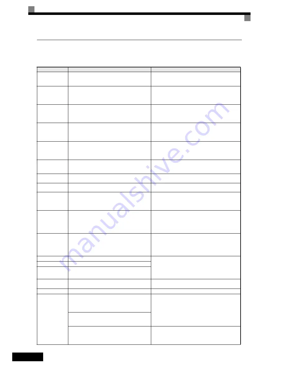
Auto-tuning Faults
Auto-tuning faults are shown below. When the following faults are detected, the fault is displayed on the dig-
ital operator and the motor coasts to stop. No fault or alarm outputs will be operated.
Display
Meaning
Corrective Actions
Accelerate
Acceleration error (detected during rotating autotuning
only)
The motor did not accelerate in the specified time.
• Increase C1-01 (Acceleration Time 1).
• Increase L7-01 and L7-02 (Torque Limits) if they are low.
• Remove the ropes and repeat the tuning.
End - 1
V/f Over Setting
V/f Settings Alarm
Displayed after auto-tuning is complete
The torque reference exceeded 100% and the no-load cur-
rent exceeded 70% during auto-tuning.
• Check and correct the motor settings
• If the motor and the machine are connected, disconnect the
motor from the machine.
End - 2
Saturation
Motor Core Saturation Fault
Displayed after auto-tuning is complete.
Detected only for rotating autotuning
• Check the input data.
• Check the motor wiring.
• If the motor and the machine are connected, disconnect the
motor from the machine.
End - 3
Rated FLA Alm
Rated Current Setting Alarm
Displayed after auto-tuning is complete
During auto-tuning, the measured value of motor rated
current (E2-01) was higher than the set value.
Check the motor rated current value.
Fault
Motor data fault
• Check the input data.
• The motor and inverter capacity do not fit. Check the Inverter
and motor capacity.
• Check the motor rated current and no-load current.
I-det. Circuit
Current detection error
The current exceeded the motor rated current or any out-
put phase is open
Check wiring of the Inverter and the mounting.
KE_ERR
(PM motor only)
Voltage constant error
Check the motor wiring
LD_ERR
(PM motor only)
Inductance error
Check the motor wiring
Leakage Induc-
tance Fault
The leakage inductance measurement caused an error.
The leakage inductance tuning current was too high or too
low (Closed Loop Vector for PM only)
• Check the motor wiring.
• Check the motor rated current input value
• Reduce or increase the current level for leakage inductance
tuning by changing parameter n8-46.
Minor Fault
Any of the above listed alarms occured during autotuning
or the inverter was in Base Block condition when the tun-
ing was started.
• Leave the tuning menu, check the alarm content and remove
the cause as described in the alarm list above.
• Check the input data.
• Make sure that the inverter is not in Base Block condition
during the tuning.
Motor Speed
Motor Speed Fault
Detected only for rotating autotuning
The torque reference exceeded 100% during acceleration.
Detected only when A1-02 is set to 2 (Open Loop Vector
control).
• If the motor is connected to the machine, disconnect it.
• Increase C1-01 (Acceleration Time 1).
• Check the input data (particularly the number of PG pulses
and the number of motor poles).
• Perform not rotating auto tuning
No-Load Current
No-Load Current Fault
• Check the input data.
• Check the motor wiring.
• If the motor is connected to the machine, disconnect it.
• If the setting of T1-03 is higher than the Inverter input power
supply voltage (E1-01), change the input data.
Resistance
Line-to-Line Resistance Fault
Rated slip
Rated Slip Fault
RS_ERR
(PM motor only)
Line-to-line resistance error
• Check the motor wiring
• Check the motor input data
STOP key
STOP key input
-
Z_SRCH_ERR
(PM motor only)
All encoders:
The motor speed exceeded 20 rpm at the auto tuning start.
The magnetic pole position tuning could not be performed
in the specified time.
• Remove the ropes and repeat the tuning
• Check the encoder rotation direction and if necessary change
F1-05.
Encoder with Z-pulse:
The difference between two measurements of the magnet
pole position was higher than 3°.
Serial encoders:
The difference between two measurements of the magnet
pole position was higher than 5° or an encoder serial com-
munication error has occurred during the tuning.
• Check the encoder wiring (order, shield etc.)
• Check the encoder power supply.
Replace the encoder.
Summary of Contents for CIMR-L7
Page 33: ...EN 31...
Page 65: ...DE 31...
Page 97: ...ES 31...
Page 129: ...FR 31...
Page 161: ...IT 31...
Page 193: ...PT 31...
Page 195: ...RU 1 Varispeed L7 5 LC RC...
Page 198: ...RU 4 2 Omron Yaskawa Motion Control Omron Yaskawa Motion Control 3 20...
Page 199: ...RU 5 Omron Yaskawa Motion Control 1 IP00 IP20 NEMA 1 2 18 5 22 50 30 30 B 120 B 50 120...
Page 200: ...RU 6 R L1 S L2 T L3 R S T 600 PE L1 L2 L3 PE GND L1 L2 L3 GND U V W M 3...
Page 209: ...RU 15 Data Invalid 50 150 27 1 2 3 4 5 BB BB1 6 7 8 9 STOP 1 2 3 4 END 60 2...
Page 215: ...RU 21 d1 18 2 d1 18 1 H1 83 d1 18 2 H1 83 d1 17 H1 K80 d1 18 2 d1 09 1 2 FRL FRL S3 09 0...
Page 217: ...RU 23 5 DOWN DOWN n5 05 0 P 1 UP DOWN 2 n5 01 3 n5 05 0 4 5...
Page 225: ...RU 31...


