Network Setup
4-31
10.Refer to the
Status
field for the current state of the requests made from applet. This field displays error
messages if something goes wrong in the transaction between the applet and the switch.
11.Click on the
Radius...
button (when Radius is selected as the accounting mode) to configure an external
or internal primary and secondary Radius and NAC server. For more information, see
Configuring External
Radius Server Support on page 4-47
.
12.Select the
Syslog
button (when Syslog is selected as the accounting mode) to view switch syslog
accounting details. To enable syslog, select the
Syslog
option from the
Accounting Mode
drop-down
menu. Use this sub screen to provide the Syslog Server IP address and port for the Syslog Server
performing the accounting function.
13.Click
OK
to use the changes to the running configuration and close the dialog.
14.Click
Cancel
to close the dialog without committing updates to the running configuration.
4.5.1.2 Assigning Multiple VLANs per WLAN
The switch allows the mapping of a WLAN to more than one VLAN. When an MU associates with a WLAN,
it is assigned a VLAN in such a way that users are load balanced across VLANs. The VLAN is assigned from
the pool representative of the WLAN. The switch tracks the number of MUs per VLAN, and assigns the least
used/loaded VLAN to the MU. This number is tracked on a per-WLAN basis.
To assign multiple VLANs to a WLAN:
1. Select
Network
>
Wireless LANs
from the main menu tree.
2. Select an existing WLAN from those displayed within the
Configuration
tab and click the
Edit
button.
A WLAN screen displays with the WLAN’s existing configuration.
3. Select the
VLAN
radio button from the Configuration screen to change the VLAN designation for this
WLAN.
By default, all WLANs are initially assigned to VLAN 1.
4. Select the
Dynamic Assignment
checkbox for a user-based VLAN assignment with Radius for this
WLAN.
5. Select the
Assign Multiple VLAN(s)
button to map a WLAN to more than one VLAN. This displays the
Multiple VLAN Mapping screen.
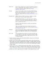
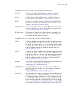
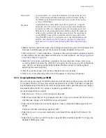
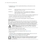
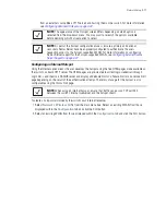
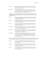
MCast Addr 2
The second address also takes packets (where the first 4 bytes match the first 4
bytes of the mask) and sends them immediately over the air instead of waiting for
the DTIM period. Any multicast/broadcast that does not match this mask will go
out only on DTIM Intervals.
NAC Mode
Using
Network Access Control
(NAC), the switch only grants access to specific
network resources. NAC restricts access to only compliant and validated devices
(printers, phones, PDAs, etc.), thereby limiting the risk of emerging security risks.
NAC performs an authorization check for users and MUs without a NAC agent, and
verifies an MU’s compliance with the network security policy. The switch supports
only the EAP/802.1x type of NAC. However, the switch can bypass NAC for MUs
without NAC 802.1x support. For the implications of using the include and exclude
with NAC, see
Configuring the NAC Inclusion List on page 4-70
,
Configuring the
NAC Exclusion List on page 4-74
and
Configuring NAC Server Support on page
4-51
.
Summary of Contents for RFS Series
Page 1: ...M Motorola RFS Series Wireless LAN Switches WiNG System Reference Guide ...
Page 10: ...TOC 8 Motorola RF Switch System Reference Guide ...
Page 56: ...2 8 Motorola RF Switch System Reference ...
Page 334: ...5 52 Motorola RF Switch System Reference 2 Select the MU Status tab ...
Page 510: ...7 32 Motorola RF Switch System Reference Guide ...
Page 534: ...8 24 Motorola RF Switch System Reference Guide ...
Page 570: ...C 14 Motorola RF Switch System Reference Guide ...
Page 589: ......

