5-14
Motorola RF Switch System Reference
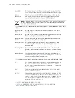
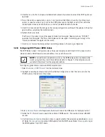
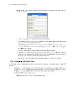
2. Click the
Relay
tab.
3. Refer to the
Interface
s field for the names of the interfaces available to route information between the
DHCP Server and DHCP clients. If this information is insufficient, consider creating a new IP pool or edit
an existing pool.
4. Click the
Edit
button to modify the properties displayed on an existing DHCP pool. Refer to step 7 for the
information that can be modified for the DHCP relay.
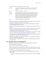
5. To delete an existing DHCP pool from the list of those available to the switch, highlight the pool from
within the Network Pool field and click the
Delete
button.
6. Click the
Add
button to create a new DHCP pool.
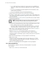
a. Use the
Interface
drop-down menu to assign the interface used for the DHCP relay. As VLANs are
added to the switch, the number of interfaces available grows.
b. Add
Servers
as needed to supply DHCP relay resources.
NOTE:
The interface VLAN and gateway interface should have their IP addresses set. The
interface VLAN and gateway interface should not have DHCP client or DHCP Server
enabled. DHCP packets cannot be relayed to an onboard DHCP Server. The interface VLAN
and gateway interface cannot be the same.
Summary of Contents for RFS Series
Page 1: ...M Motorola RFS Series Wireless LAN Switches WiNG System Reference Guide ...
Page 10: ...TOC 8 Motorola RF Switch System Reference Guide ...
Page 56: ...2 8 Motorola RF Switch System Reference ...
Page 334: ...5 52 Motorola RF Switch System Reference 2 Select the MU Status tab ...
Page 510: ...7 32 Motorola RF Switch System Reference Guide ...
Page 534: ...8 24 Motorola RF Switch System Reference Guide ...
Page 570: ...C 14 Motorola RF Switch System Reference Guide ...
Page 589: ......

