Switch Services
5-37
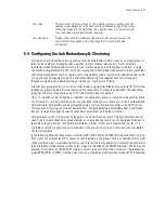
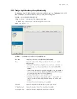
3. To enable
Dynamic AP Load Balancing
check the
Enable Dynamic AP Load Balancing
box and
configure the parameters below:
4. Once Dynamic Load Balancing parameters are set, click the
Dynamic AP LB Now
button to run Dynamic
AP Load Balancing.
5. Managing clustering in the Web UI is done through the
Cluster GUI
feature. Check the
Enable Cluster
GUI
checkbox to enable this feature. The
Cluster GUI
feature updates many key screens in the Web UI
allowing you to see APs and MUs managed by all active members of a cluster.
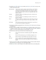
6. Refer to the
History
field to view the current state of the redundancy group.
7. Click
Apply
to save any changes to the screen. Navigating away from the screen without clicking the
Apply button results in all the changes on the screen being discarded.
8. Click the
Revert
button to undo the changes to the screen and revert to the last saved configuration.
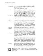
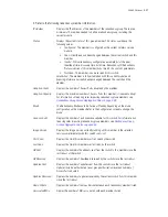
Runtime/Schedule
Select Runtime or Schedule to determine when load balancing will run. If Runtime
is selected, load balancing will initiate anytime a new active switch is added to
the redundancy group. If Schedule is selected you can configure a start date and
time to execute load balancing. This feature is not available when Dynamic Load
Balancing is enabled.
Start Date
If Schedule is selected as the load balancing mode, enter a start date for load
balancing to take place.
Start Time
If Schedule is selected as the load balancing mode, enter a start time for load
balancing to take place.
Interval
If Schedule is selected as the load balancing mode, enter an interval (in days) for
how often load balancing should take place. The valid range is between 1 and 180
days.
MU Threshold
The MU threshold specifies the number of minimum number of active MUs on an
AP to stop the AP from resetting for load balancing.
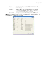
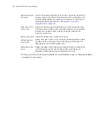
State
Displays the new state (status) of the redundancy group after a Trigger event has
occurred.
Time
Displays the Timestamp (time zone specific) when the state change occurred.
Trigger
Displays the event causing the redundancy group state change on the switch.
Description
Displays a redundancy event description defining the redundancy group state
change on the switch. Typical states include Redundancy Disabled or Redundancy
Enabled.
Summary of Contents for RFS Series
Page 1: ...M Motorola RFS Series Wireless LAN Switches WiNG System Reference Guide ...
Page 10: ...TOC 8 Motorola RF Switch System Reference Guide ...
Page 56: ...2 8 Motorola RF Switch System Reference ...
Page 334: ...5 52 Motorola RF Switch System Reference 2 Select the MU Status tab ...
Page 510: ...7 32 Motorola RF Switch System Reference Guide ...
Page 534: ...8 24 Motorola RF Switch System Reference Guide ...
Page 570: ...C 14 Motorola RF Switch System Reference Guide ...
Page 589: ......

