4-92
Motorola RF Switch System Reference Guide
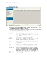
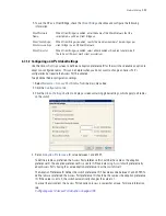
2. Click the
Configuration
tab.
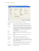
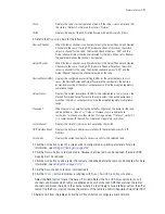
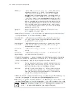
3. Refer to the table for the following information:
Switch
The
Switch
field displays the IP address of the cluster member associated with
each Access Port radio. When clustering is enabled on the switch and Cluster GUI
is enabled, the
Switch
field will be available on the Access Port radio
configuration screen. For information on configuring enabling Cluster GUI, see
Managing Clustering Using the Web UI
.
Index
Displays the numerical index (device identifier) used with the device radio. Use
this index (along with the radio name) to differentiate the radio from other device
radios.
Description
Displays a user-assigned name for the radio.
AP Type
Displays the type of Access Port detected. The switches support Motorola AP 100,
AP300 and AP650 model Access Ports and AP-4131, AP-5131 and AP-7131 model
Access Points.
Type
Use the Type to identify whether the radio is 802.11b, 802.11bg and 802.11bgn or
802.11a and 802.11an.
Adopted
Displays the radio’s adoption status. If the radio is adopted, a green check
displays. If the radio is not adopted, a red X displays.
Parent AP MAC
Address
Displays the Access Port's Ethernet MAC (the device MAC address that is printed
on the casing of the unit). Do not confuse this BSSID MAC with the Access Port's
Ethernet MAC address.
MAC Address
The Base Radio MAC is the radio's first MAC address when it is adopted by the
Switch.
Summary of Contents for RFS Series
Page 1: ...M Motorola RFS Series Wireless LAN Switches WiNG System Reference Guide ...
Page 10: ...TOC 8 Motorola RF Switch System Reference Guide ...
Page 56: ...2 8 Motorola RF Switch System Reference ...
Page 334: ...5 52 Motorola RF Switch System Reference 2 Select the MU Status tab ...
Page 510: ...7 32 Motorola RF Switch System Reference Guide ...
Page 534: ...8 24 Motorola RF Switch System Reference Guide ...
Page 570: ...C 14 Motorola RF Switch System Reference Guide ...
Page 589: ......

