Network Setup
4-81
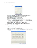
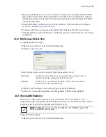
3. Click the
Details
button to launch a screen with additional information about the selected MU. For more
information, see
Viewing MU Details on page 4-81
4. Highlight an MU from those listed and click the
Disconnect
button to remove the MU from the list of
currently associated devices.
Be aware that disconnected MUs will often become immediately re-connected to the switch. Ensure that
disconnected MUs are permanently removed from switch association.
5. Click the
Export
button to export the content of the table to a
Comma Separated Values
file (CSV).
6. Click the
Edit MAC Name
button and it will open a window where you can associate a name with the
selected MU's MAC Address. The MAC Name is a user-created name used to identify individual mobile
unit MAC Addresses with a user-friendly name or description.
7. Click the
dot11k
button and it will open a new window where you can configure 802.11k Radio Resource
Management services.
4.6.1.1 Viewing MU Details
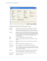
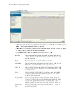
The
MUs Details
screen displays read-only MU transmit and receive statistics.
To view MU Details:
1. Select a
Network
>
Mobile Units
from the main menu tree.
2. Click the
Status
tab.
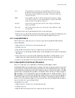
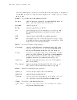
MAC Name
Displays the MAC name associated with each MU's MAC Address. The MAC
Name is a user-created name used to identify individual mobile unit MAC
Addresses with a user-friendly name.
IP Address
Displays the unique IP address for the MU. Use this address as necessary
throughout the applet for filtering and device intrusion recognition and approval.
Ready
Displays whether the MU is ready for switch interoperation. Values are Yes and
No.
Session Timeout
Displays the session timeout values for each of the listed MUs.
Power Save
Displays the current (read-only)
Power-Save-Poll
(PSP) state of the MU. The
Power Save
field has two potential settings. PSP indicates that the MU is
operating in Power Save Protocol mode. In PSP, the MU runs enough power to
check for beacons and is otherwise inactive. CAM indicates that the MU is
continuously aware of all radio traffic. CAM is recommended for MUs frequently
transmitting with the switch’s Access Ports for periods of two hours or greater.
WLAN
Displays the name of the WLAN the MU’s associated AP is connect to.
VLAN
Displays the specific VLAN the target MU is mapped to.
Tunnel
Displays the tunnel the target MU is mapped to.
Radio Index
The Radio Index is a numerical device recognition identifier for MU radios. The
index is helpful to differentiate device radios when a particular MU has more than
one radio.
Radio Type
The Radio Type defines the radio used by the adopted MU. The switch supports
802.11a, 802.11b, and 802.11g single radio MUs as well as dual radio 802.11ab,
802.11bg, 802.11an, and 802.11bgn MUs.
Summary of Contents for RFS Series
Page 1: ...M Motorola RFS Series Wireless LAN Switches WiNG System Reference Guide ...
Page 10: ...TOC 8 Motorola RF Switch System Reference Guide ...
Page 56: ...2 8 Motorola RF Switch System Reference ...
Page 334: ...5 52 Motorola RF Switch System Reference 2 Select the MU Status tab ...
Page 510: ...7 32 Motorola RF Switch System Reference Guide ...
Page 534: ...8 24 Motorola RF Switch System Reference Guide ...
Page 570: ...C 14 Motorola RF Switch System Reference Guide ...
Page 589: ......


