Statistic Data Generation
MOTOROLA
CMOS Sensor Interface Module
31-13
31.6 Statistic Data Generation
The statistic block generates a simple set of normalized totals for the red, blue, and green pixels contained
in the image. The software uses these values to control the auto exposure (AE) and auto white balance
(AWB) of the camera. The block also generates a sum of absolute differences of the green pixels for each
block that is used to determine the relative focus of the image by creating this rough measure for contrast.
31.6.1 Statistic Block Diagram and Description
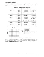
Figure 31-2. Statistic Block Diagram
31.6.2 Auto Exposure and Auto White Balance
The values are based on the supported live view image resolutions in the range of 512
×
384 to 288
×
216
pixels.
These image sizes are divided up into square blocks of varying size to produce an array of 8
×
6 values for
each color in all cases. The sum of each color pixel values in each block is temporary saved in the 8
×
18
register. Depending on the DRM bit of the CSI Control Register 2, the sum value is either divided by 4
(DRM = 0) or 2 (DRM = 1) before it is stored in the FIFO. The SOAD (sum of absolute difference) data is
generated by the SOAD block and temporarily stored in an 8
×
18 register. The DRM bit of the Control
Register 2 determines the amount of division to be done on the SOAD data before it is stored in the FIFO.
The block size for the corresponding live view LCD size is shown in Table 31-11 on page 31-14.
NOTE:
For the 384
×
256 live view, the statistic array is only 6
×
4 and uses a larger
block size. This is due to the 3:2 ratio of the CCD vs. the 4:3 ratio of the
rest of the CCDs.
CONTROL SIGNAL
LVRM
BTS
DRM
SOF
StatControl
Counter
FSM
StatValidMask
SCE
HSC
VSC
AFS
STAT_DATA
_REQ
BAYER_DATA
BAYER_DATA
_VALID
ST
A
T
_
F
IF
O
PIXEL TOTAL
8x18
Reg
8x1
mux
Adder
G_stat
B_stat
R_stat
F_stat
Pixel Total
Pixel Total
Pixel Total
G1 Reg
G2 Reg
|G1-G2|
SOAD
STAT_DATA
_OUT
STAT_FIFO
_FULL
Summary of Contents for DragonBall MC9328MX1
Page 68: ...1 12 MC9328MX1 Reference Manual MOTOROLA Introduction ...
Page 86: ...2 18 MC9328MX1 Reference Manual MOTOROLA Signal Descriptions and Pin Assignments ...
Page 116: ...3 30 MC9328MX1 Reference Manual MOTOROLA Memory Map ...
Page 126: ...4 10 MC9328MX1 Reference Manual MOTOROLA ARM920T Processor ...
Page 160: ...8 8 MC9328MX1 Reference Manual MOTOROLA System Control ...
Page 272: ...13 32 MC9328MX1 Reference Manual MOTOROLA DMA Controller ...
Page 281: ...Programming Model MOTOROLA Watchdog Timer Module 14 9 ...
Page 282: ...14 10 MC9328MX1 Reference Manual MOTOROLA Watchdog Timer Module ...
Page 300: ...15 18 MC9328MX1 Reference Manual MOTOROLA Analog Signal Processor ASP ...
Page 438: ...18 16 MC9328MX1 Reference Manual MOTOROLA Serial Peripheral Interface Modules SPI 1 and SPI 2 ...
Page 478: ...19 40 MC9328MX1 Reference Manual MOTOROLA LCD Controller ...
Page 574: ...21 32 MC9328MX1 Reference Manual MOTOROLA Memory Stick Host Controller MSHC Module ...
Page 598: ...23 16 MC9328MX1 Reference Manual MOTOROLA Real Time Clock RTC ...
Page 670: ...24 72 MC9328MX1 Reference Manual MOTOROLA SDRAM Memory Controller ...
Page 726: ...25 56 MC9328MX1 Reference Manual MOTOROLA SmartCard Interface Module SIM ...
Page 736: ...26 10 MC9328MX1 Reference Manual MOTOROLA General Purpose Timers ...
Page 854: ...29 18 MC9328MX1 Reference Manual MOTOROLA I2C Module ...
Page 900: ...30 46 MC9328MX1 Reference Manual MOTOROLA Synchronous Serial Interface SSI ...
Page 942: ...32 26 MC9328MX1 Reference Manual MOTOROLA GPIO Module and I O Multiplexer IOMUX ...


