Programming Model
MOTOROLA
Phase-Locked Loop and Clock Controller
12-11
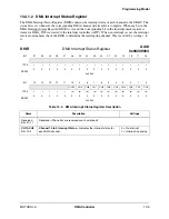
12.5.3.2 MCU PLL and System Clock Control Register 1
The MCU PLL and System Clock Control Register 1 (MPCTL1) is a 32-bit register that directs the
operation of the on-chip MCU PLL. The MPCTL1 control bits are described in Table 12-10.
12.5.4 Generation of 48 MHz Clocks
The USB interface clock (CLK48M) is used internally by the USB module. Its frequency is set to 48 MHz
using the PLL control registers assuming a default input clock frequency 16.384 MHz. This input clock
frequency assumes a 32 kHz crystal input.
The predivider/multiplier output depends on the input clock frequency as shown in Table 12-11.
MPCTL1
MCU PLL and System Clock Control Register 1
Addr
0x0021B008
BIT
31
30 29
28
27
26
25
24
23
22
21
20
19
18
17
16
TYPE
r
r
r
r
r
r
r
r
r
r
r
r
r
r
r
r
RESET
0
0
0
0
0
0
0
0
0
0
0
0
0
0
0
0
0x0000
BIT
15
14 13
12
11
10
9
8
7
6
5
4
3
2
1
0
BRMO
TYPE
r
r
r
r
r
r
r
r
r
rw
r
r
r
r
r
r
RESET
0
0
0
0
0
0
0
0
0
0
0
0
0
0
0
0
0x0000
Table 12-10. MCU PLL and System Clock Control Register 1 Description
Name
Description
Settings
Reserved
Bits 31–7
Reserved—These bits are reserved and should read 0.
BRMO
Bit 6
BRM Order
—Controls the BRM order. The first order BRM is used if a
MF fractional part is both more than 1/10 and less than 9/10. In other
cases, the second order BRM is used. The BRMO bit is cleared by a
hardware reset. A delay of reference cycles is required between two write
accesses to BRMO.
0 = BRM contains
first order
1 = BRM contains
second order
Reserved
Bits 5–0
Reserved—These bits are reserved and should read 0.
Table 12-11. System PLL Multiplier Factor
PLL
Input
Frequency
Premultiplier
PD
MFD
MFI
MFN
PLL
Output
Frequency
USBDIV
USB
Clock
Frequency
32 kHz
16.384 MHz
1
63
5
55
96 MHz
2
48 MHz
The default setting exception is USB_DIV. The user must program this to 010.
Summary of Contents for DragonBall MC9328MX1
Page 68: ...1 12 MC9328MX1 Reference Manual MOTOROLA Introduction ...
Page 86: ...2 18 MC9328MX1 Reference Manual MOTOROLA Signal Descriptions and Pin Assignments ...
Page 116: ...3 30 MC9328MX1 Reference Manual MOTOROLA Memory Map ...
Page 126: ...4 10 MC9328MX1 Reference Manual MOTOROLA ARM920T Processor ...
Page 160: ...8 8 MC9328MX1 Reference Manual MOTOROLA System Control ...
Page 272: ...13 32 MC9328MX1 Reference Manual MOTOROLA DMA Controller ...
Page 281: ...Programming Model MOTOROLA Watchdog Timer Module 14 9 ...
Page 282: ...14 10 MC9328MX1 Reference Manual MOTOROLA Watchdog Timer Module ...
Page 300: ...15 18 MC9328MX1 Reference Manual MOTOROLA Analog Signal Processor ASP ...
Page 438: ...18 16 MC9328MX1 Reference Manual MOTOROLA Serial Peripheral Interface Modules SPI 1 and SPI 2 ...
Page 478: ...19 40 MC9328MX1 Reference Manual MOTOROLA LCD Controller ...
Page 574: ...21 32 MC9328MX1 Reference Manual MOTOROLA Memory Stick Host Controller MSHC Module ...
Page 598: ...23 16 MC9328MX1 Reference Manual MOTOROLA Real Time Clock RTC ...
Page 670: ...24 72 MC9328MX1 Reference Manual MOTOROLA SDRAM Memory Controller ...
Page 726: ...25 56 MC9328MX1 Reference Manual MOTOROLA SmartCard Interface Module SIM ...
Page 736: ...26 10 MC9328MX1 Reference Manual MOTOROLA General Purpose Timers ...
Page 854: ...29 18 MC9328MX1 Reference Manual MOTOROLA I2C Module ...
Page 900: ...30 46 MC9328MX1 Reference Manual MOTOROLA Synchronous Serial Interface SSI ...
Page 942: ...32 26 MC9328MX1 Reference Manual MOTOROLA GPIO Module and I O Multiplexer IOMUX ...

