Index-x
MC9328MX1 Reference Manual
MOTOROLA
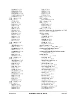
INTREG
x
register
BO bit, 18-11
BOEN bit, 18-10
RF bit, 18-11
RFEN bit, 18-10
RH bit, 18-11
RHEN bit, 18-10
RO bit, 18-11
ROEN bit, 18-10
RR bit, 18-11
RREN bit, 18-10
TE bit, 18-11
TEEN bit, 18-10
TF bit, 18-11
TFEN bit, 18-10
TH bit, 18-11
THEN bit, 18-10
Introduction, 1-1
INTSRCH register, 10-26
INTSRCL register, 10-27
INTTYPE field, 10-14
,
10-15
INTTYPEH register, 10-14
INTTYPEL register, 10-15
IRQEN bit, 26-5
ISR_A register, 32-22
ISR_B register, 32-22
ISR_C register, 32-22
ISR_D register, 32-22
ISR_
x
register
ISR field, 32-22
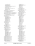
J
Joint detect registers, 16-87
L
LCD color cursor mapping register,
see
LCHCC register
LCD cursor position,
see
CPOS register
LCD cursor width height and blink register,
see
LCWHB register
LCD gray palette mapping register,
see
LSCR1 register
LCDC
active matrix panel interface signals
"digital CRT", 19-14
active matrix panel interface signals, 19-14
active panel interface timing, 19-16
black-and-white operation, 19-7
color generation, 19-8
display data mapping, 19-3
features, 19-1
frame rate modulation control, 19-10
gray scale operation, 19-7
introduction, 19-1
mapping RAM registers, 19-37
operation, 19-2
panel interface signals, 19-10
panning
typical panning algorithm, 19-3
panning, 19-3
passive panel interface timing, 19-13
pin configuration
setting data direction, 19-11
pin configuration, 19-11
programming model, 19-18
screen format
maximum page width, 19-3
screen format, 19-2
using VPH for boundary checks, 19-3
LCDICR register
INTCON bit, 19-35
INTSYN bit, 19-35
LCDICR register, 19-35
LCDISR register
BOF bit, 19-36
EOF bit, 19-36
ERR_RES bit, 19-36
UDR_ERR bit, 19-36
LCDISR register, 19-36
LCHCC register
CUR_COL_B register, 19-29
CUR_COL_G register, 19-29
CUR_COL_R register, 19-29
LCHCC register, 19-29
LCWHB register
BD field, 19-28
BK_EN bit, 19-28
CH field, 19-28
CW field, 19-28
LCWHB register, 19-28
LENGTH field, 17-17
,
17-21
LGPMR register,
see
LSCR1 register
Linear redundancy check okay flag,
see
LRCOK bit
LRC enable,
see
LRCEN bit
LRCEN bit, 25-24
LRCOK bit, 25-29
LSCR1 register
GRAY 2 register, 19-31
CLS_RISE_DELAY field, 19-30
GRAY 1 register, 19-31
PS_RISE_DELAY field, 19-30
REV_TOGGLE_DELAY field, 19-30
Summary of Contents for DragonBall MC9328MX1
Page 68: ...1 12 MC9328MX1 Reference Manual MOTOROLA Introduction ...
Page 86: ...2 18 MC9328MX1 Reference Manual MOTOROLA Signal Descriptions and Pin Assignments ...
Page 116: ...3 30 MC9328MX1 Reference Manual MOTOROLA Memory Map ...
Page 126: ...4 10 MC9328MX1 Reference Manual MOTOROLA ARM920T Processor ...
Page 160: ...8 8 MC9328MX1 Reference Manual MOTOROLA System Control ...
Page 272: ...13 32 MC9328MX1 Reference Manual MOTOROLA DMA Controller ...
Page 281: ...Programming Model MOTOROLA Watchdog Timer Module 14 9 ...
Page 282: ...14 10 MC9328MX1 Reference Manual MOTOROLA Watchdog Timer Module ...
Page 300: ...15 18 MC9328MX1 Reference Manual MOTOROLA Analog Signal Processor ASP ...
Page 438: ...18 16 MC9328MX1 Reference Manual MOTOROLA Serial Peripheral Interface Modules SPI 1 and SPI 2 ...
Page 478: ...19 40 MC9328MX1 Reference Manual MOTOROLA LCD Controller ...
Page 574: ...21 32 MC9328MX1 Reference Manual MOTOROLA Memory Stick Host Controller MSHC Module ...
Page 598: ...23 16 MC9328MX1 Reference Manual MOTOROLA Real Time Clock RTC ...
Page 670: ...24 72 MC9328MX1 Reference Manual MOTOROLA SDRAM Memory Controller ...
Page 726: ...25 56 MC9328MX1 Reference Manual MOTOROLA SmartCard Interface Module SIM ...
Page 736: ...26 10 MC9328MX1 Reference Manual MOTOROLA General Purpose Timers ...
Page 854: ...29 18 MC9328MX1 Reference Manual MOTOROLA I2C Module ...
Page 900: ...30 46 MC9328MX1 Reference Manual MOTOROLA Synchronous Serial Interface SSI ...
Page 942: ...32 26 MC9328MX1 Reference Manual MOTOROLA GPIO Module and I O Multiplexer IOMUX ...


