20-4
MC9328MX1 Reference Manual
MOTOROLA
Multimedia Card/Secure Digital Host Controller Module (MMC/SD)
NOTE:
The SD I/O card contains additional registers that are not included in
Table 20-2.
20.4.2 Communication
The MMC/SD module and the card communicate via commands, responses, and data bytes, defined as
follows:
•
Commands
—Commands initiate operations. Commands are transferred serially on the SD_CMD
line from the MMC/SD module to a single card or to all cards. Each command token is preceded by
a start bit (
0
) and concluded by an end bit (1). The total length of a command is 48 bits, and is
protected by CRC bits.
•
Responses
—Responses are answers to commands and cannot be initiated. Responses are
transferred serially on the SD_CMD lines from a single addressed card or multiple responses can
be sent synchronously from all cards to the MMC/SD module. The format of each response varies
based on the command that initiated the response. See Section 20.7.8.5, “Response Formats,” for
more information.
•
Data
—Data is transferred via the SD_DAT line(s) from the card to the MMC/SD module or from
the MMC/SD module to the card. Not all operations include data transfer.
Both
DSR
Driver Stage
Configures the card’s output drivers. Usage is
optional, not required.
16
Both
CSD
Card Specific Data
Contains information on the card’s operating
conditions.
128
1
Both
OCR
Operation Conditions
Indicates the card’s operating voltage range.
Detects restricted cards and indicates whether
power-up is complete. Usage is optional, not
required.
32
Both
CSR
Card Status Register
Contains card’s error and status information.
Sent to the MMC/SD module in response format
R1.
32
SD only
SCS
SD Card Status
Contains status information proprietary to the SD
card (such as protection, card type, and bus
width).
512
SD only
SCR
SD Configuration Register
Contains additional configuration information
only applicable to the SD card.
64
1.
There can be fewer bits for the SD I/O Card, depending on implementation (see
SDIO Card Specification,
version 1.0 for more information).
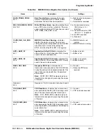
Table 20-2. MMC/SD Card Registers (Continued)
MMC or SD
Identifier
Register Name
Description
Size
(Bits)
Summary of Contents for DragonBall MC9328MX1
Page 68: ...1 12 MC9328MX1 Reference Manual MOTOROLA Introduction ...
Page 86: ...2 18 MC9328MX1 Reference Manual MOTOROLA Signal Descriptions and Pin Assignments ...
Page 116: ...3 30 MC9328MX1 Reference Manual MOTOROLA Memory Map ...
Page 126: ...4 10 MC9328MX1 Reference Manual MOTOROLA ARM920T Processor ...
Page 160: ...8 8 MC9328MX1 Reference Manual MOTOROLA System Control ...
Page 272: ...13 32 MC9328MX1 Reference Manual MOTOROLA DMA Controller ...
Page 281: ...Programming Model MOTOROLA Watchdog Timer Module 14 9 ...
Page 282: ...14 10 MC9328MX1 Reference Manual MOTOROLA Watchdog Timer Module ...
Page 300: ...15 18 MC9328MX1 Reference Manual MOTOROLA Analog Signal Processor ASP ...
Page 438: ...18 16 MC9328MX1 Reference Manual MOTOROLA Serial Peripheral Interface Modules SPI 1 and SPI 2 ...
Page 478: ...19 40 MC9328MX1 Reference Manual MOTOROLA LCD Controller ...
Page 574: ...21 32 MC9328MX1 Reference Manual MOTOROLA Memory Stick Host Controller MSHC Module ...
Page 598: ...23 16 MC9328MX1 Reference Manual MOTOROLA Real Time Clock RTC ...
Page 670: ...24 72 MC9328MX1 Reference Manual MOTOROLA SDRAM Memory Controller ...
Page 726: ...25 56 MC9328MX1 Reference Manual MOTOROLA SmartCard Interface Module SIM ...
Page 736: ...26 10 MC9328MX1 Reference Manual MOTOROLA General Purpose Timers ...
Page 854: ...29 18 MC9328MX1 Reference Manual MOTOROLA I2C Module ...
Page 900: ...30 46 MC9328MX1 Reference Manual MOTOROLA Synchronous Serial Interface SSI ...
Page 942: ...32 26 MC9328MX1 Reference Manual MOTOROLA GPIO Module and I O Multiplexer IOMUX ...


