11-8
MC9328MX1 Reference Manual
MOTOROLA
External Interface Module (EIM)
11.5 EIM Functionality
11.5.1 Configurable Bus Sizing
The EIM supports byte, halfword, and word operands, allowing access to 8-bit ports, 16-bit ports, and
32-bit ports. It does not support misaligned transfers.
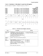
The port size is programmable via the DSZ bits in the corresponding chip select control register. In
addition, the portion of the data bus used for transfer to or from an 8-bit port or 16-bit port is
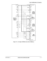
programmable via the same bits. An 8-bit port can reside on external data bus bits D [31:24], D [23:16], D
[15:8] or D [7:0]. A 16-bit port can reside on external data bus bits D [31:16] or D [15:0].
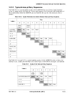
Word access to or from an 8-bit port requires four external bus cycles to complete the transfer. Word
access to or from a 16-bit port requires two external bus cycles to complete the transfer. Half-word access
to or from an 8-bit port requires two external bus cycles to complete the transfer. In the case of a
multi-cycle transfer, the lower two address bits, A [1:0], are incremented appropriately.
The EIM has a data multiplexer that routes the four bytes of the AHB interface data bus to the required
positions to allow proper interfacing to memory and peripherals.
11.5.2 Programmable Output Generation
Unused chip select outputs can be configured to provide a programmable output signal. This functionality
is not provided for the CS [0] output signal. When the CSEN bit is cleared, CS [0] is always inactive. To
operate as a programmable output pin, the corresponding CSEN control bit must be cleared.
11.5.3 Burst Mode Operation
When burst mode is enabled, the EIM attempts to burst read data from as many sequential address
locations as possible, limited only by the length of the burst flash internal page buffer, or the
non-sequential nature of the ARM920T processor code or data stream. The EIM only displays the first
address accessed in a burst sequence unless the page mode emulation (PME) bit is set.
For the first access in a burst sequence, the EIM asserts load burst address (LBA), causing the external
burst device to latch the starting burst address, and then toggles the burst clock (BCLK) for a predefined
number of cycles to latch the first unit of data. Subsequently read data units are burst from the external
device in fewer clock cycles, realizing an overall increase in bus bandwidth.
Burst accesses is terminated by the EIM when it detects that the next ARM920T processor access is not
sequential in nature, or when the external burst device needs additional cycles to retrieve the next
requested memory location. In the latter case, the burst flash device provides an ECB signal to the EIM
whenever it must terminate the on-going burst sequence and initiate a new (long first access) burst
sequence.
11.5.4 Burst Clock Divisor
In some cases it is necessary to slow the external bus in relation to the internal bus to allow accesses to
burst devices that have a maximum operating frequency that is lower than the operating frequency of the
internal AHB bus. The internal bus frequency can be divided by 2, 3, or 4 for presentation on the external
bus in burst mode operation.
Summary of Contents for DragonBall MC9328MX1
Page 68: ...1 12 MC9328MX1 Reference Manual MOTOROLA Introduction ...
Page 86: ...2 18 MC9328MX1 Reference Manual MOTOROLA Signal Descriptions and Pin Assignments ...
Page 116: ...3 30 MC9328MX1 Reference Manual MOTOROLA Memory Map ...
Page 126: ...4 10 MC9328MX1 Reference Manual MOTOROLA ARM920T Processor ...
Page 160: ...8 8 MC9328MX1 Reference Manual MOTOROLA System Control ...
Page 272: ...13 32 MC9328MX1 Reference Manual MOTOROLA DMA Controller ...
Page 281: ...Programming Model MOTOROLA Watchdog Timer Module 14 9 ...
Page 282: ...14 10 MC9328MX1 Reference Manual MOTOROLA Watchdog Timer Module ...
Page 300: ...15 18 MC9328MX1 Reference Manual MOTOROLA Analog Signal Processor ASP ...
Page 438: ...18 16 MC9328MX1 Reference Manual MOTOROLA Serial Peripheral Interface Modules SPI 1 and SPI 2 ...
Page 478: ...19 40 MC9328MX1 Reference Manual MOTOROLA LCD Controller ...
Page 574: ...21 32 MC9328MX1 Reference Manual MOTOROLA Memory Stick Host Controller MSHC Module ...
Page 598: ...23 16 MC9328MX1 Reference Manual MOTOROLA Real Time Clock RTC ...
Page 670: ...24 72 MC9328MX1 Reference Manual MOTOROLA SDRAM Memory Controller ...
Page 726: ...25 56 MC9328MX1 Reference Manual MOTOROLA SmartCard Interface Module SIM ...
Page 736: ...26 10 MC9328MX1 Reference Manual MOTOROLA General Purpose Timers ...
Page 854: ...29 18 MC9328MX1 Reference Manual MOTOROLA I2C Module ...
Page 900: ...30 46 MC9328MX1 Reference Manual MOTOROLA Synchronous Serial Interface SSI ...
Page 942: ...32 26 MC9328MX1 Reference Manual MOTOROLA GPIO Module and I O Multiplexer IOMUX ...


