Programming Model
MOTOROLA
Phase-Locked Loop and Clock Controller
12-9
12.5.3 Programming Digital Phase Locked Loops
There are two DPLLs in the MC9328MX1—the MCU PLL and the System PLL. The MCU PLL primarily
generates FCLK to the CPU, and the System PLL derives all system clocks to the entire MC9328MX1 and
generates clocks that produce the programmable frequency range required by modules such as the USB,
UARTs, and SSI.
The MCU PLL derives the ARM920T processor’s CPU clock FCLK, and the System PLL derives the
ARM920T processor’s CPU clock BCLK, as well as the system clocks PERCLK 1, 2, and 3, and HCLK.
The MCU PLL frequency is determined by the speed requirement of the ARM920T processor. The
recommended settings for both MCU PLL and System PLL, which produces the least amount of signal
jitter, are shown in Table 12-8.
12.5.3.1 MCU PLL Control Register 0
The MCU PLL Control Register 0 (MPCTL0) is a 32-bit register that controls the operation of the MCU
PLL. The MPCTL0 control bits are described in the following sections. A delay of 56 FCLK cycles (about
10–30 FCLK cycles for MCU PLL controller plus 2–26 FCLK cycles are necessary to get EDRAM_IDLE
and SDRAM_IDLE signals) is required between two write accesses to MPCTL0 register. The following is
a procedure for changing the MCU PLL settings:
1. Program the desired values of PD, MFD, MFI, and MFN into the MPCTL0.
2. Set the MPLL_RESTART bit in the CSCR (it will self-clear).
3. New PLL settings will take place.
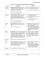
PCLK_DIV1
Bits 3
–
0
Peripheral Clock Divider 1
—Contains the 4-bit integer divider that
produces the PERCLK1 clock signal for the peripherals. The input to
the PCLK_DIV1 divider circuit is System PLLCLK.
0000 = Divide by 1
0001 = Divide by 2
…
1111 = Divide by 16
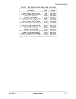
Table 12-8. Sample Frequency Table
PLL Input
Frequency
Premultiplier
PD
MFD
MFI
MFN
PLL Output
Frequency
32 kHz
16.384 MHz
0
63
5
55
192 MHz
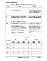
Table 12-7. Peripheral Clock Divider Register Description (Continued)
Name
Description
Settings
Summary of Contents for DragonBall MC9328MX1
Page 68: ...1 12 MC9328MX1 Reference Manual MOTOROLA Introduction ...
Page 86: ...2 18 MC9328MX1 Reference Manual MOTOROLA Signal Descriptions and Pin Assignments ...
Page 116: ...3 30 MC9328MX1 Reference Manual MOTOROLA Memory Map ...
Page 126: ...4 10 MC9328MX1 Reference Manual MOTOROLA ARM920T Processor ...
Page 160: ...8 8 MC9328MX1 Reference Manual MOTOROLA System Control ...
Page 272: ...13 32 MC9328MX1 Reference Manual MOTOROLA DMA Controller ...
Page 281: ...Programming Model MOTOROLA Watchdog Timer Module 14 9 ...
Page 282: ...14 10 MC9328MX1 Reference Manual MOTOROLA Watchdog Timer Module ...
Page 300: ...15 18 MC9328MX1 Reference Manual MOTOROLA Analog Signal Processor ASP ...
Page 438: ...18 16 MC9328MX1 Reference Manual MOTOROLA Serial Peripheral Interface Modules SPI 1 and SPI 2 ...
Page 478: ...19 40 MC9328MX1 Reference Manual MOTOROLA LCD Controller ...
Page 574: ...21 32 MC9328MX1 Reference Manual MOTOROLA Memory Stick Host Controller MSHC Module ...
Page 598: ...23 16 MC9328MX1 Reference Manual MOTOROLA Real Time Clock RTC ...
Page 670: ...24 72 MC9328MX1 Reference Manual MOTOROLA SDRAM Memory Controller ...
Page 726: ...25 56 MC9328MX1 Reference Manual MOTOROLA SmartCard Interface Module SIM ...
Page 736: ...26 10 MC9328MX1 Reference Manual MOTOROLA General Purpose Timers ...
Page 854: ...29 18 MC9328MX1 Reference Manual MOTOROLA I2C Module ...
Page 900: ...30 46 MC9328MX1 Reference Manual MOTOROLA Synchronous Serial Interface SSI ...
Page 942: ...32 26 MC9328MX1 Reference Manual MOTOROLA GPIO Module and I O Multiplexer IOMUX ...

