Watchdog Control
MOTOROLA
Watchdog Timer Module
14-3
14.3.4 Time-Out
If the counter reaches zero, the TOUT bit in WSTR (Watchdog Status Register) is set to 1 indicating that
watchdog has timed out. Reading the TOUT bit will clear it.
If the counter reaches zero, the watchdog asserts either a system reset signal WDT_RST or an interrupt
request signal WDT_INT depending on the state of the WIE bit in the WCR. A 1 written to WIE
configures the watchdog to generate a interrupt request signal to the interrupt handler. When a watchdog
time-out interrupt is asserted, the TINT bit in WSTR (Watchdog Status Register) is set to 1 to indicate that
an interrupt request is generated and the reading of this bit clears the interrupt and this bit. A 0 written to
the WIE bit configures the watchdog to generate a WDT_RST signal to reset the module. The counter state
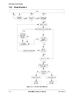
machine is shown in Figure 14-2 on page 14-4.
14.3.5 Halting the Counter
The watchdog counting can be halted at any time by setting the WHALT bit (WCR[15]) to 1. The counter
immediately stops counting and the counter value is held at the last value. The WHALT bit can be cleared
by writing 0 to it or it can be automatically cleared by the occurrence of any of three system events, fast
interrupt, slow interrupt, or system reset. The counter resumes counting from the stopped value. No other
configurations are affected.
14.4 Watchdog Control
14.4.1 Interrupt Control
The watchdog timer generates interrupt request signal WDT_INT as a result of a WDOG time-out when
WIE bit of WCR set to 1. The TINT bit of WSTR is set to 1 to indicate that the interrupt request has been
generated. Reading the TINT bit clears the interrupt and this status bit.
14.4.2 Reset Sources
The watchdog timer generates reset signal WDT_RST as a result of a WDOG time-out. This signal is an
output to the Reset Module for system reset generation.
Summary of Contents for DragonBall MC9328MX1
Page 68: ...1 12 MC9328MX1 Reference Manual MOTOROLA Introduction ...
Page 86: ...2 18 MC9328MX1 Reference Manual MOTOROLA Signal Descriptions and Pin Assignments ...
Page 116: ...3 30 MC9328MX1 Reference Manual MOTOROLA Memory Map ...
Page 126: ...4 10 MC9328MX1 Reference Manual MOTOROLA ARM920T Processor ...
Page 160: ...8 8 MC9328MX1 Reference Manual MOTOROLA System Control ...
Page 272: ...13 32 MC9328MX1 Reference Manual MOTOROLA DMA Controller ...
Page 281: ...Programming Model MOTOROLA Watchdog Timer Module 14 9 ...
Page 282: ...14 10 MC9328MX1 Reference Manual MOTOROLA Watchdog Timer Module ...
Page 300: ...15 18 MC9328MX1 Reference Manual MOTOROLA Analog Signal Processor ASP ...
Page 438: ...18 16 MC9328MX1 Reference Manual MOTOROLA Serial Peripheral Interface Modules SPI 1 and SPI 2 ...
Page 478: ...19 40 MC9328MX1 Reference Manual MOTOROLA LCD Controller ...
Page 574: ...21 32 MC9328MX1 Reference Manual MOTOROLA Memory Stick Host Controller MSHC Module ...
Page 598: ...23 16 MC9328MX1 Reference Manual MOTOROLA Real Time Clock RTC ...
Page 670: ...24 72 MC9328MX1 Reference Manual MOTOROLA SDRAM Memory Controller ...
Page 726: ...25 56 MC9328MX1 Reference Manual MOTOROLA SmartCard Interface Module SIM ...
Page 736: ...26 10 MC9328MX1 Reference Manual MOTOROLA General Purpose Timers ...
Page 854: ...29 18 MC9328MX1 Reference Manual MOTOROLA I2C Module ...
Page 900: ...30 46 MC9328MX1 Reference Manual MOTOROLA Synchronous Serial Interface SSI ...
Page 942: ...32 26 MC9328MX1 Reference Manual MOTOROLA GPIO Module and I O Multiplexer IOMUX ...


