27-14
MC9328MX1 Reference Manual
MOTOROLA
Universal Asynchronous Receiver/Transmitters (UART) Modules
The vote logic captures a sample on every rising edge of BRM_CLK, however the receiver uses 16x
oversampling to take its value in the middle of the sample frame. The idle character may be longer or
shorter than 16 counts, however the receiver looks for a 1-to-0 transition. The receiver starts to count when
the Start bit is set however it does not capture the contents of the RxFIFO at the time the Start bit is set. The
start bit is validated when 0s are received for 7 consecutive bit times following the 1-to-0 transition. Once
the counter reaches 0xF, it starts counting on the next bit and captures it in the middle of the sampling
frame (see Figure 27-4). All data bits are captured in the same manner. Once the stop bit is detected, the
receiver shift register (SIPO_OUT) data is parallel shifted to the RxFIFO.
There is a special case when the BRM_CLK period is longer than the period of the IR 0 pulse (when the
baud rate is configured for less than 31.25 Kbps). In this case, the software sets the IRSC bit so that the
MC9328MX1 reference clock is the clock for the voting logic. The pulse is validated by counting the
length of the pulse. This logic only works with 16 MHz, 25 MHz, and 30 MHz reference clock
frequencies. Enabling this bit with any other reference frequency is undefined. When setting IRSC
=
1,
either:
•
Ignore the first character received, clear the status flags after the RDR bit is set, and proceed,
•
OR enables the software reset of the UART module after the initial configuration of UART
including setting of the reference frequency bit (Ref16/Ref25/Ref30), however before setting IRSC
bit to high. Using this method, insures the first character received is correct.
27.5.8 Binary Rate Multiplier (BRM)
The BRM submodule generates all baud rates that required integer and non-integer division. The input and
output frequency ratio is programmed in the UART BRM Incremental Register (UBIR_1/UBIR_2) and
UART BRM MOD Register (UBMR_1/UBMR_2). The output frequency is divided by the input
frequency to produce this ratio. For integer division, set the UBIR_1/UBIR_2
=
0x000F and write the
divisor to the UBMR_1/UBMR_2 register. All values written to these registers must be one less than the
actual value to eliminate division by 0 (undefined), and to increase the maximum range of the registers.
Updating the BRM registers requires writing to both registers. The UBIR_1/UBIR_2 register must be
written before writing to the UBMR_1/UBMR_2 register. If only one register is written to by the software,
the BRM continues to use the previous values.
The following examples show how to determine what values are to be programmed into UBIR and UBMR
for a given reference frequency and desired baud rate. The following equation can be used to help
determine these values:
[(Desired Baud Rate)*16]/(reference frequency)=NUM/DENOM
Eqn. 27-1
UBIR = NUM - 1
Eqn. 27-2
UBMR = DENOM - 1
Eqn. 27-3
reference frequency = PERCLK1 / RFDIV [2:0]
Eqn. 27-4
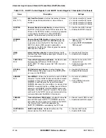
Table 27-7. Majority Vote Results
Samples
Vote
000
0
101
1
001
0
111
1
Summary of Contents for DragonBall MC9328MX1
Page 68: ...1 12 MC9328MX1 Reference Manual MOTOROLA Introduction ...
Page 86: ...2 18 MC9328MX1 Reference Manual MOTOROLA Signal Descriptions and Pin Assignments ...
Page 116: ...3 30 MC9328MX1 Reference Manual MOTOROLA Memory Map ...
Page 126: ...4 10 MC9328MX1 Reference Manual MOTOROLA ARM920T Processor ...
Page 160: ...8 8 MC9328MX1 Reference Manual MOTOROLA System Control ...
Page 272: ...13 32 MC9328MX1 Reference Manual MOTOROLA DMA Controller ...
Page 281: ...Programming Model MOTOROLA Watchdog Timer Module 14 9 ...
Page 282: ...14 10 MC9328MX1 Reference Manual MOTOROLA Watchdog Timer Module ...
Page 300: ...15 18 MC9328MX1 Reference Manual MOTOROLA Analog Signal Processor ASP ...
Page 438: ...18 16 MC9328MX1 Reference Manual MOTOROLA Serial Peripheral Interface Modules SPI 1 and SPI 2 ...
Page 478: ...19 40 MC9328MX1 Reference Manual MOTOROLA LCD Controller ...
Page 574: ...21 32 MC9328MX1 Reference Manual MOTOROLA Memory Stick Host Controller MSHC Module ...
Page 598: ...23 16 MC9328MX1 Reference Manual MOTOROLA Real Time Clock RTC ...
Page 670: ...24 72 MC9328MX1 Reference Manual MOTOROLA SDRAM Memory Controller ...
Page 726: ...25 56 MC9328MX1 Reference Manual MOTOROLA SmartCard Interface Module SIM ...
Page 736: ...26 10 MC9328MX1 Reference Manual MOTOROLA General Purpose Timers ...
Page 854: ...29 18 MC9328MX1 Reference Manual MOTOROLA I2C Module ...
Page 900: ...30 46 MC9328MX1 Reference Manual MOTOROLA Synchronous Serial Interface SSI ...
Page 942: ...32 26 MC9328MX1 Reference Manual MOTOROLA GPIO Module and I O Multiplexer IOMUX ...


