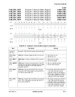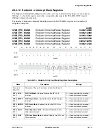
Programming Model
MOTOROLA
USB Device Port
28-11
28.3.4 USB Control Register
The USB Control Register configures numerous features of the USB module.
USB_CTRL
USB Control Register
Addr
0x0021200C
BIT
31
30
29
28
27
26
25
24
23
22
21
20
19
18
17
16
TYPE
r
r
r
r
r
r
r
r
r
r
r
r
r
r
r
r
RESET
0
0
0
0
0
0
0
0
0
0
0
0
0
0
0
0
0x0000
BIT
15
14
13
12
11
10
9
8
7
6
5
4
3
2
1
0
CMD_
OVER
CMD_
ERROR
USB_
SPD
USB_
ENA
UDC_
RST
AFE_
ENA
RESUME
TYPE
r
r
r
r
r
r
r
r
r
rw
rw
rw
rw
w
rw
w
RESET
0
0
0
0
0
0
0
0
0
0
0
1
0
0
0
0
0x0010
Table 28-7. USB Control Register Description
Name
Description
Settings
Reserved
Bits 31–7
Reserved—These bits are reserved and should read 0.
CMD_OVER
Bit 6
Command Over
—Indicates status of command
processing. See Table 28-8 for more information.
CMD_OVER clears automatically after the UDC core has
completed the status phase of a control transfer.
0 = Command complete
1 = Command in process
CMD_ERROR
Bit 5
Command Error
—Indicates if an error was encountered
during processing of a device request. See Table 28-8 for
more information. CMD_OVER and CMD_ERROR
combine to create the handshaking code for the status
phase of a device request transaction.
0 = If the command was processed,
there was no error
1 = If the command was processed,
an error occurred
USB_SPD
Bit 4
USB Speed
—Sets the operating speed for the USB
module.
Note:
The USB module supports only full speed
operation of the device. Attempts to set to slow speed
results in unpredictable operation.
0 = Low speed
1 = Full speed
USB_ENA
Bit 3
USB Enable
—Determines whether the USB module
responds to requests from the USB host. The USB module
comes out of reset in the disabled state. The user must
ensure that the USB endpoint configuration and USB
registers are programmed appropriately before enabling
communications. USB_ENA does not affect the underlying
UDC core, only the front-end logic’s ability to communicate
with the core.
0 = USB module front-end logic is
disabled. All transactions to or
from the UDC are ignored.
1 = USB module front-end logic is
enabled and ready to
communicate with the host.
Summary of Contents for DragonBall MC9328MX1
Page 68: ...1 12 MC9328MX1 Reference Manual MOTOROLA Introduction ...
Page 86: ...2 18 MC9328MX1 Reference Manual MOTOROLA Signal Descriptions and Pin Assignments ...
Page 116: ...3 30 MC9328MX1 Reference Manual MOTOROLA Memory Map ...
Page 126: ...4 10 MC9328MX1 Reference Manual MOTOROLA ARM920T Processor ...
Page 160: ...8 8 MC9328MX1 Reference Manual MOTOROLA System Control ...
Page 272: ...13 32 MC9328MX1 Reference Manual MOTOROLA DMA Controller ...
Page 281: ...Programming Model MOTOROLA Watchdog Timer Module 14 9 ...
Page 282: ...14 10 MC9328MX1 Reference Manual MOTOROLA Watchdog Timer Module ...
Page 300: ...15 18 MC9328MX1 Reference Manual MOTOROLA Analog Signal Processor ASP ...
Page 438: ...18 16 MC9328MX1 Reference Manual MOTOROLA Serial Peripheral Interface Modules SPI 1 and SPI 2 ...
Page 478: ...19 40 MC9328MX1 Reference Manual MOTOROLA LCD Controller ...
Page 574: ...21 32 MC9328MX1 Reference Manual MOTOROLA Memory Stick Host Controller MSHC Module ...
Page 598: ...23 16 MC9328MX1 Reference Manual MOTOROLA Real Time Clock RTC ...
Page 670: ...24 72 MC9328MX1 Reference Manual MOTOROLA SDRAM Memory Controller ...
Page 726: ...25 56 MC9328MX1 Reference Manual MOTOROLA SmartCard Interface Module SIM ...
Page 736: ...26 10 MC9328MX1 Reference Manual MOTOROLA General Purpose Timers ...
Page 854: ...29 18 MC9328MX1 Reference Manual MOTOROLA I2C Module ...
Page 900: ...30 46 MC9328MX1 Reference Manual MOTOROLA Synchronous Serial Interface SSI ...
Page 942: ...32 26 MC9328MX1 Reference Manual MOTOROLA GPIO Module and I O Multiplexer IOMUX ...


