Functional Programming Example
MOTOROLA
SmartCard Interface Module (SIM)
25-43
25.7.3 Configuring the SIM Transmitter
Table 25-28 provides the steps to configure the SIM transmitter for operation and the cross references for
identifying the specific section for additional reference.
3.
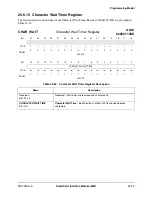
Configure the Character Wait Time Counter:
a. Program character wait time interval in the CHAR_WAIT register.
b. Enable character wait time counter by setting the CWTEN bit in the
CNTL register.
Section , “,” on page 25-39
Section 25.6.2, “Control Register,”
on page 25-23
4.
Enable interrupts:
a. Enable the receive data register full interrupt through the RIM bit in
the INT_MASK register.
b. Enable the overrun condition interrupt through the OIM bit in the
INT_MASK register.
c. Enable the character wait time interrupt through the CWTM bit in
the INT_MASK register.
Section 25.6.7, “Interrupt Mask
Register,” on page 25-31
Table 25-28. Configuring the SIM Transmitter
Step
Action
Reference
1.
Select desired re-transmission threshold for NACKed characters in
the XMT_THRESHOLD register. Program the threshold at which the
XTE flag is set through the XTH bits.
Section , “,” on page 25-35
2.
Select the guard time between transmissions in the GUARD_CNTL
register. Program the desired guard time between characters
transmitted by the SIM through the GETU bits.
Section , “,” on page 25-36
3.
Select the desired transmit FIFO threshold level in the
XMT_THRESHOLD register. Program the desired threshold through
the TDT bits.
Section , “,” on page 25-35
4.
Enable interrupts in the INT_MASK register:
a. Enable the transmit complete interrupt through the TCIM
bit.
b. Enable the early transmit complete interrupt through the ETCIM
bit.
c. Enable the transmit FIFO empty interrupt through the TFEIM
bit.
d. Enable the transmit threshold error interrupt through the XTM bit.
e. Enable the transmit FIFO threshold interrupt through the TDTFM
bit.
f. Enable the transmit FIFO overfill interrupt through the TFOM bit.
Section 25.6.7, “Interrupt Mask
Register,” on page 25-31
Table 25-27. Configuring the SIM Receiver (Continued)
Step
Action
Reference
Summary of Contents for DragonBall MC9328MX1
Page 68: ...1 12 MC9328MX1 Reference Manual MOTOROLA Introduction ...
Page 86: ...2 18 MC9328MX1 Reference Manual MOTOROLA Signal Descriptions and Pin Assignments ...
Page 116: ...3 30 MC9328MX1 Reference Manual MOTOROLA Memory Map ...
Page 126: ...4 10 MC9328MX1 Reference Manual MOTOROLA ARM920T Processor ...
Page 160: ...8 8 MC9328MX1 Reference Manual MOTOROLA System Control ...
Page 272: ...13 32 MC9328MX1 Reference Manual MOTOROLA DMA Controller ...
Page 281: ...Programming Model MOTOROLA Watchdog Timer Module 14 9 ...
Page 282: ...14 10 MC9328MX1 Reference Manual MOTOROLA Watchdog Timer Module ...
Page 300: ...15 18 MC9328MX1 Reference Manual MOTOROLA Analog Signal Processor ASP ...
Page 438: ...18 16 MC9328MX1 Reference Manual MOTOROLA Serial Peripheral Interface Modules SPI 1 and SPI 2 ...
Page 478: ...19 40 MC9328MX1 Reference Manual MOTOROLA LCD Controller ...
Page 574: ...21 32 MC9328MX1 Reference Manual MOTOROLA Memory Stick Host Controller MSHC Module ...
Page 598: ...23 16 MC9328MX1 Reference Manual MOTOROLA Real Time Clock RTC ...
Page 670: ...24 72 MC9328MX1 Reference Manual MOTOROLA SDRAM Memory Controller ...
Page 726: ...25 56 MC9328MX1 Reference Manual MOTOROLA SmartCard Interface Module SIM ...
Page 736: ...26 10 MC9328MX1 Reference Manual MOTOROLA General Purpose Timers ...
Page 854: ...29 18 MC9328MX1 Reference Manual MOTOROLA I2C Module ...
Page 900: ...30 46 MC9328MX1 Reference Manual MOTOROLA Synchronous Serial Interface SSI ...
Page 942: ...32 26 MC9328MX1 Reference Manual MOTOROLA GPIO Module and I O Multiplexer IOMUX ...


