Memory Stick Host Controller Operation
MOTOROLA
Memory Stick Host Controller (MSHC) Module
21-7
The detection of INT from the Memory Stick occurs in following conditions:
1. MC9328MX1 is in Normal operation mode or Doze mode and the MSHC module is enabled
(MSCEN bit is set).
2. Under condition 1, the MSHC module is in Normal operation mode (PWS bit = 0).
3. The MSHC module recognizes INT when the SDIO remains high for 3 SCLK cycles during
BS0.
21.5.4 Reset Operation
The Memory Stick Control/Status Register’s RST bit (MSCS [RST]) provides a mechanism for software
resets. When 1 is written to the RST bit, the MSHC module is reset and an associated I/O reset is initiated.
A value of
1
is maintained for the RST bit for more than SCLK 2 clocks and then must be returned to 0 to
perform reset in synchronization with the clock.
A reset of the MSHC module results in:
1. Register operation (Status after RST = 1 and immediately after RST = 0)
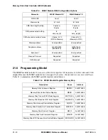
— Memory Stick Command Register (MSCMD) = 0x0000
— Memory Stick Control/Status Register (MSCS) = 0x050A
— Memory Stick Receive FIFO Data Register (MSRDATA) and Memory Stick Transmit FIFO
Data Register (MSTDATA) = 0x0000
— Memory Stick Interrupt Control/Status Register (MSICS) = 0x0080
— Memory Stick Parallel Port Control/Data Register (MSPPCD) = 0x0000
— Memory Stick Control 2 Register (MSC2) = ACD, RED and LEND bit = 0. MSCEN bit is not
changed
— Memory Stick Auto Command Register (MSACD) = 0x7001
— Memory Stick FIFO Access Error Control/Status Register (MSFAECS) = 0x0000
— Memory Stick Serial Clock Divider Register (MSCLKD) = no change
— Memory Stick DMA Request Control Register (MSDRQC) = 0x0000
2. Output signal status
— MS_BS —>
Low level
— MS_SDIO_OUT —>
Low level
— MS_SCLK —>
Low level
3. Internal operation
— Internal Interrupt Request signal (MSIRQ) —>
High level (Negated)
— Internal DMA Request signal —> High level (Negated)
— The Transmit/Receive FIFOs are cleared
4. The executing protocol is terminated
Summary of Contents for DragonBall MC9328MX1
Page 68: ...1 12 MC9328MX1 Reference Manual MOTOROLA Introduction ...
Page 86: ...2 18 MC9328MX1 Reference Manual MOTOROLA Signal Descriptions and Pin Assignments ...
Page 116: ...3 30 MC9328MX1 Reference Manual MOTOROLA Memory Map ...
Page 126: ...4 10 MC9328MX1 Reference Manual MOTOROLA ARM920T Processor ...
Page 160: ...8 8 MC9328MX1 Reference Manual MOTOROLA System Control ...
Page 272: ...13 32 MC9328MX1 Reference Manual MOTOROLA DMA Controller ...
Page 281: ...Programming Model MOTOROLA Watchdog Timer Module 14 9 ...
Page 282: ...14 10 MC9328MX1 Reference Manual MOTOROLA Watchdog Timer Module ...
Page 300: ...15 18 MC9328MX1 Reference Manual MOTOROLA Analog Signal Processor ASP ...
Page 438: ...18 16 MC9328MX1 Reference Manual MOTOROLA Serial Peripheral Interface Modules SPI 1 and SPI 2 ...
Page 478: ...19 40 MC9328MX1 Reference Manual MOTOROLA LCD Controller ...
Page 574: ...21 32 MC9328MX1 Reference Manual MOTOROLA Memory Stick Host Controller MSHC Module ...
Page 598: ...23 16 MC9328MX1 Reference Manual MOTOROLA Real Time Clock RTC ...
Page 670: ...24 72 MC9328MX1 Reference Manual MOTOROLA SDRAM Memory Controller ...
Page 726: ...25 56 MC9328MX1 Reference Manual MOTOROLA SmartCard Interface Module SIM ...
Page 736: ...26 10 MC9328MX1 Reference Manual MOTOROLA General Purpose Timers ...
Page 854: ...29 18 MC9328MX1 Reference Manual MOTOROLA I2C Module ...
Page 900: ...30 46 MC9328MX1 Reference Manual MOTOROLA Synchronous Serial Interface SSI ...
Page 942: ...32 26 MC9328MX1 Reference Manual MOTOROLA GPIO Module and I O Multiplexer IOMUX ...


