Module Descriptions
MOTOROLA
Bluetooth Accelerator (BTA)
16-11
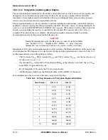
16.3.1.3.3 Whitening/De-Whitening
According to the Bluetooth specifications, all packets must be scrambled to randomize the data from
highly redundant patterns and to minimize DC bias in the packet. The whitening unit performs this
scrambling (whitening) and descrambling (de-whitening) of the packet header and payload (including the
CRC) during transmit and receive.
Whitening is enabled or disabled by software. To enable whitening, write the initialization word specified
in the Bluetooth standard to the WHITE_CONTROL register. To disable, write all zeros to the same
register. There is no status information available for the whitening/de-whitening unit.
16.3.1.3.4 FEC Coding/Decoding
The forward error correction (FEC) is a standard block encoder/decoder algorithm. Two forms of FEC are
used in the Bluetooth standard:
•
1/3 FEC: Repeating each bit so that each bit occurs three times in a row. Simple majority decision
is used in decoding—that is, if two or more bits are equal, the value of these bits is used.
•
2/3 FEC: Using a (15, 10) shortened Hamming code with a minimum distance of 4. This encoding
allows correction of one-bit errors and detection of two-bit errors. For each block of 10 bits, 5
redundant bits are appended. In the receive decoding, the BTA checks each 15 bit block for errors
and sets the REC2 and NREC flags in the status register accordingly.
FEC can be enabled or disabled by software according to the packet type.
16.3.1.4 Bit Buffer
The bit buffer is a 512-bit memory bank used for four different purposes. It is software accessible, and is
arranged as eight 64-bit “long words,” designated
LW0
through
LW7
. Software views each long word as
four concatenated 16 bit words that are accessed independently. Figure 16-4 illustrates the arrangement of
the long words in the bit buffer.
11
CL[1]
CL[0]
12
111000CL
25
CL
24
CL[2]
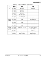
Table 16-5. Writing Sequence for Encryption Engine Initialization (Continued)
Word Number
Bits 15–8
Bits 7–0
Summary of Contents for DragonBall MC9328MX1
Page 68: ...1 12 MC9328MX1 Reference Manual MOTOROLA Introduction ...
Page 86: ...2 18 MC9328MX1 Reference Manual MOTOROLA Signal Descriptions and Pin Assignments ...
Page 116: ...3 30 MC9328MX1 Reference Manual MOTOROLA Memory Map ...
Page 126: ...4 10 MC9328MX1 Reference Manual MOTOROLA ARM920T Processor ...
Page 160: ...8 8 MC9328MX1 Reference Manual MOTOROLA System Control ...
Page 272: ...13 32 MC9328MX1 Reference Manual MOTOROLA DMA Controller ...
Page 281: ...Programming Model MOTOROLA Watchdog Timer Module 14 9 ...
Page 282: ...14 10 MC9328MX1 Reference Manual MOTOROLA Watchdog Timer Module ...
Page 300: ...15 18 MC9328MX1 Reference Manual MOTOROLA Analog Signal Processor ASP ...
Page 438: ...18 16 MC9328MX1 Reference Manual MOTOROLA Serial Peripheral Interface Modules SPI 1 and SPI 2 ...
Page 478: ...19 40 MC9328MX1 Reference Manual MOTOROLA LCD Controller ...
Page 574: ...21 32 MC9328MX1 Reference Manual MOTOROLA Memory Stick Host Controller MSHC Module ...
Page 598: ...23 16 MC9328MX1 Reference Manual MOTOROLA Real Time Clock RTC ...
Page 670: ...24 72 MC9328MX1 Reference Manual MOTOROLA SDRAM Memory Controller ...
Page 726: ...25 56 MC9328MX1 Reference Manual MOTOROLA SmartCard Interface Module SIM ...
Page 736: ...26 10 MC9328MX1 Reference Manual MOTOROLA General Purpose Timers ...
Page 854: ...29 18 MC9328MX1 Reference Manual MOTOROLA I2C Module ...
Page 900: ...30 46 MC9328MX1 Reference Manual MOTOROLA Synchronous Serial Interface SSI ...
Page 942: ...32 26 MC9328MX1 Reference Manual MOTOROLA GPIO Module and I O Multiplexer IOMUX ...

