3 - 31
Chapter 3 Specifications and Functions
2
A
L1
L2
L3
U
W
V
L11
L21
CN1A
CN1B
DICOM
ALM
EM2/1
DOCOM
MR-J4-B
Ra2
SM
24VDC
U
V
W
Ground
Electro-
magnetic
brake
0
B
L1
L2
L3
U
W
V
L11
L21
CN1A
CN1B
DICOM
ALM
EM2/1
DOCOM
MR-J4-B
Ra3
SM
24VDC
U
V
W
Ground
Electro-
magnetic
brake
1
C
L1
L2
L3
U
W
V
L11
L21
CN1A
CN1B
DICOM
ALM
EM2/1
DOCOM
MR-J4-B
Ra4
SM
24VDC
U
V
W
Ground
Electro-
magnetic
brake
MC3
SSCNET (/H)
3
4
2
3
4
2
3
4
2
6
Ra2
Ra3
Ra4
MCCB4
MC2
6
MCCB3
MC1
6
MCCB2
POINT
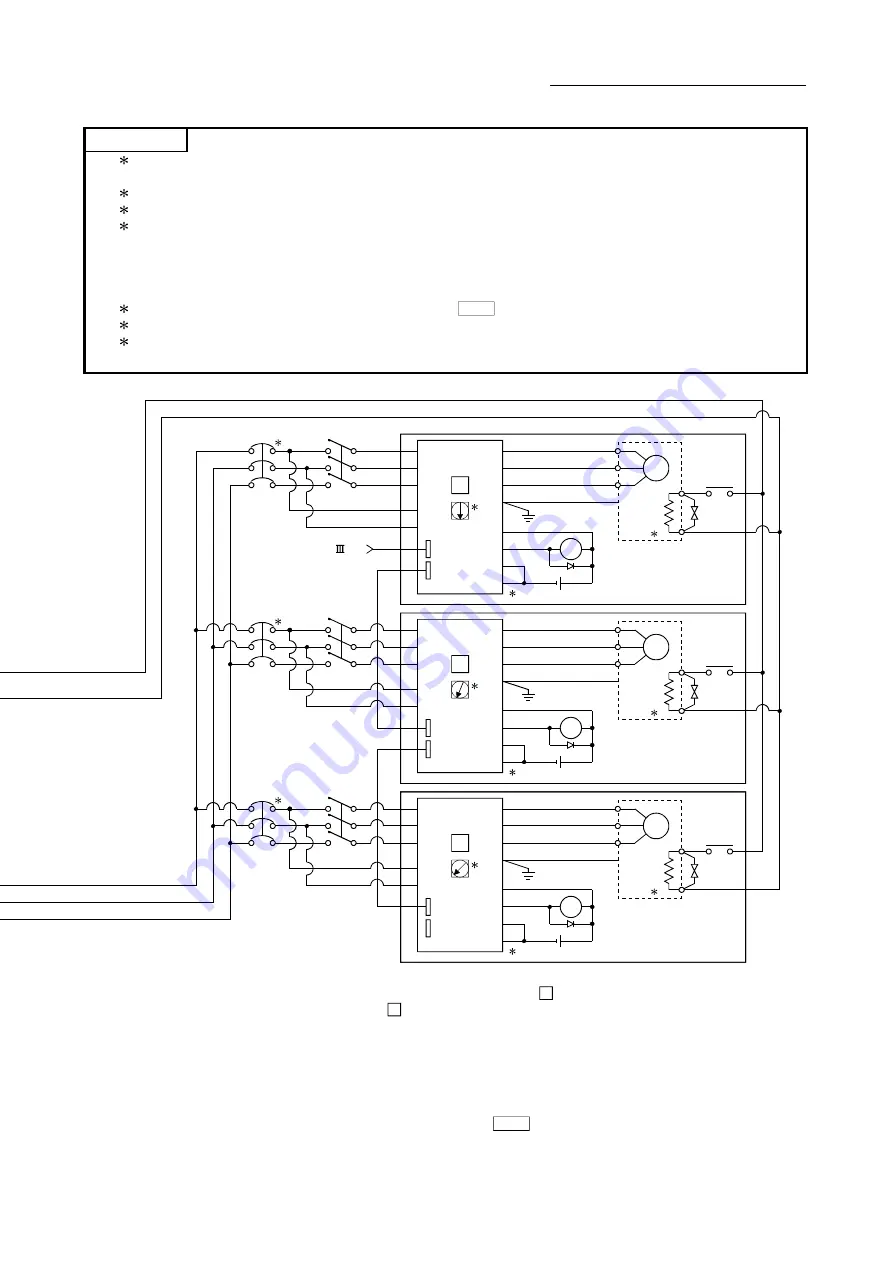
(1) 1: Configure up the power supply circuit which switch off the electromagnetic contactor (MC) after detection alarm occurrence on
the PLC CPU.
(2) 2: It is also possible to use a full wave rectified power supply as the power supply for the electromagnetic brake.
(3) 3: It is also possible to use forced stop signal of the servo amplifier.
(4) 4: Set the rotary axis setting switch of servo amplifier as follows to set the axis No. of servo amplifier.
• Axis 1: 0
• Axis 5: 4
• Axis 9: 8
• Axis 13: C
• Axis 2: 1
• Axis 6: 5
• Axis 10: 9
• Axis 14: D
• Axis 3: 2
• Axis 7: 6
• Axis 11: A
• Axis 15: E
• Axis 4: 3
• Axis 8: 7
• Axis 12: B
• Axis 16: F
(5) 5: The status of forced stop input signal can be confirmed with " Md.50
Forced stop input".
(6) 6: Refer to the servo amplifier instruction manual for selection of the circuit breaker and electromagnetic contactor.
(7) 7: The surge suppressor is recommended to be used for an AC relay or electromagnetic contactor (MC) near the servo amplifier.
Refer to the servo amplifier instruction manual for selection of the circuit breakers and magnetic contractors for wiring.
(Note-1) : When the control power supply of servo amplifier is shut off, it is not possible to communicate with the servo amplifier after that.
Example) When the control power supply L11/L21 of servo amplifier in above
B
figure is shut off, it is also not possible to
communicate with the servo amplifier
C
.
If only a specific servo amplifier main circuit power supply is shut off, be sure to shut off the main circuit power supply
L1/L2/L3, and do not shut off the control power supply L11/L21.
(Note-2) : Be sure to shut off the both of main circuit power supply L1/L2/L3 and control power supply L11/L21 after disconnection of
SSCNET communication by the connect/disconnect function of SSCNET communication at the time of exchange of servo
amplifier. At this time, it is not possible to communicate between the servo amplifier and QD77MS. Therefore, be sure to
exchange the servo amplifier after stopping the operating of machine beforehand.
(Note-3) : If the emergency stop signal of QD77MS turns OFF when setting of "
Pr.82
Forced stop valid/invalid selection" to "0 : Valid",
servomotor is stopped with dynamic brake. (The LED display of servo amplifier indicates "E7.1" (Controller forced stop input
warning).)
Summary of Contents for MELSEC-Q QD77MS
Page 1: ......
Page 27: ...A 26 MEMO...
Page 29: ...MEMO...
Page 101: ...3 34 Chapter 3 Specifications and Functions MEMO...
Page 232: ...5 111 Chapter 5 Data Used for Positioning Control MEMO...
Page 315: ...5 194 Chapter 5 Data Used for Positioning Control MEMO...
Page 337: ...6 22 Chapter 6 Sequence Program Used for Positioning Control...
Page 338: ...6 23 Chapter 6 Sequence Program Used for Positioning Control...
Page 339: ...6 24 Chapter 6 Sequence Program Used for Positioning Control...
Page 340: ...6 25 Chapter 6 Sequence Program Used for Positioning Control...
Page 341: ...6 26 Chapter 6 Sequence Program Used for Positioning Control...
Page 342: ...6 27 Chapter 6 Sequence Program Used for Positioning Control...
Page 343: ...6 28 Chapter 6 Sequence Program Used for Positioning Control...
Page 344: ...6 29 Chapter 6 Sequence Program Used for Positioning Control...
Page 345: ...6 30 Chapter 6 Sequence Program Used for Positioning Control...
Page 346: ...6 31 Chapter 6 Sequence Program Used for Positioning Control...
Page 347: ...6 32 Chapter 6 Sequence Program Used for Positioning Control...
Page 348: ...6 33 Chapter 6 Sequence Program Used for Positioning Control...
Page 349: ...6 34 Chapter 6 Sequence Program Used for Positioning Control...
Page 353: ...6 38 Chapter 6 Sequence Program Used for Positioning Control...
Page 354: ...6 39 Chapter 6 Sequence Program Used for Positioning Control...
Page 357: ...6 42 Chapter 6 Sequence Program Used for Positioning Control...
Page 359: ...6 44 Chapter 6 Sequence Program Used for Positioning Control...
Page 360: ...6 45 Chapter 6 Sequence Program Used for Positioning Control...
Page 361: ...6 46 Chapter 6 Sequence Program Used for Positioning Control...
Page 363: ...6 48 Chapter 6 Sequence Program Used for Positioning Control...
Page 364: ...6 49 Chapter 6 Sequence Program Used for Positioning Control...
Page 413: ...MEMO...
Page 433: ...8 20 Chapter 8 OPR Control MEMO...
Page 458: ...9 25 Chapter 9 Major Positioning Control MEMO...
Page 593: ...10 30 Chapter 10 High Level Positioning Control MEMO...
Page 625: ...11 32 Chapter 11 Manual Control MEMO...
Page 659: ...12 34 Chapter 12 Expansion Control MEMO...
Page 767: ...13 108 Chapter 13 Control Sub Functions MEMO...
Page 813: ...14 46 Chapter 14 Common Functions MEMO...
Page 831: ...15 18 Chapter 15 Dedicated Instructions MEMO...
Page 846: ...16 15 Chapter 16 Troubleshooting MEMO...
Page 892: ...16 61 Chapter 16 Troubleshooting MEMO...
Page 971: ...Appendix 62 Appendices MEMO...
Page 974: ......
Page 975: ......


