


5. PARAMETERS
5 - 73
No./symbol/
name
Setting
digit
Function
Initial
value
[unit]
Control
mode
P S T
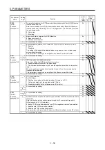
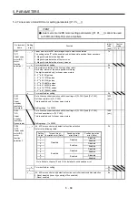
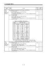
Po08
*ODO1
MR-D01
output device
selection 1
Any output device can be assigned to the CN10-46 pin and CN10-47 pin.
_ _ x x CN10-46 selection
Select an output signal function of the CN10-46 pin.
Refer to table 5.15 for settings.
This parameter setting is available with MR-J4-_A_-RJ servo amplifiers with software
version B7 or later.
26h
x x _ _ CN10-47 selection
Select an output signal function of the CN10-47 pin.
Refer to table 5.15 for settings.
This parameter setting is available with MR-J4-_A_-RJ servo amplifiers with software
version B7 or later.
27h
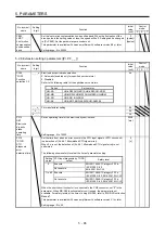
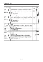
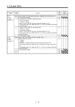
Table 5.15 Selectable output devices
Setting
value
Output device (Note)
P S T
00 Always off
Always off
Always off
02
RD RD RD
03
ALM ALM ALM
04
INP SA
Always
off
05
MBR MBR MBR
06
DB DB DB
07
TLC TLC VLC
08
WNG WNG WNG
09
BWNG BWNG BWNG
0A
Always off
SA
Always off
0B
Always off
Always off
VLC
0C
ZSP ZSP ZSP
0D
MTTR MTTR MTTR
0F
CDPS
Always off
Always off
10
CDLS
Always off
Always off
11
ABSV
Always off
Always off
Note. P: Position control mode, S: Speed control mode, T: Torque control mode
The diagonal lines indicate manufacturer settings. Never change the setting.
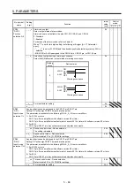
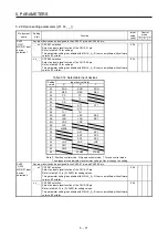
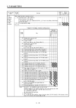
Po09
*ODO9
MR-D01
output device
selection 2
Any output device can be assigned to the CN10-48 pin and CN10-49 pin.
_ _ x x CN10-48 selection
Select an output signal function of the CN10-48 pin.
Refer to table 5.15 in [Pr. Po08] for settings.
This parameter setting is available with MR-J4-_A_-RJ servo amplifiers with software
version B7 or later.
23h
x x _ _ CN10-49 selection
Select an output signal function of the CN10-49 pin.
Refer to table 5.15 in [Pr. Po08] for settings.
This parameter setting is available with MR-J4-_A_-RJ servo amplifiers with software
version B7 or later.
04h
Summary of Contents for MR-J4-100A(-RJ)
Page 19: ...10 MEMO ...
Page 75: ...1 FUNCTIONS AND CONFIGURATION 1 56 MEMO ...
Page 83: ...2 INSTALLATION 2 8 MEMO ...
Page 159: ...3 SIGNALS AND WIRING 3 76 MEMO ...
Page 203: ...4 STARTUP 4 44 MEMO ...
Page 351: ...7 SPECIAL ADJUSTMENT FUNCTIONS 7 40 MEMO ...
Page 365: ...8 TROUBLESHOOTING 8 14 MEMO ...
Page 387: ...9 DIMENSIONS 9 22 MEMO ...
Page 403: ...10 CHARACTERISTICS 10 16 MEMO ...
Page 553: ...12 ABSOLUTE POSITION DETECTION SYSTEM 12 30 MEMO ...
Page 567: ...13 USING STO FUNCTION 13 14 MEMO ...
Page 607: ...14 COMMUNICATION FUNCTION MITSUBISHI ELECTRIC GENERAL PURPOSE AC SERVO PROTOCOL 14 40 MEMO ...
Page 639: ...15 USING A LINEAR SERVO MOTOR 15 32 MEMO ...
Page 767: ...18 MR J4 03A6 RJ SERVO AMPLIFIER 18 84 MEMO ...
Page 856: ...APPENDIX App 41 ...
Page 905: ...MEMO ...


