18. MR-J4-03A6(-RJ) SERVO AMPLIFIER
18 - 1
18. MR-J4-03A6(-RJ) SERVO AMPLIFIER
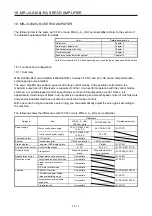
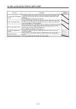
The following item is the same as 100 W or more MR-J4-_A_(-RJ) servo amplifiers. Refer to the section of
the detailed explanation field for details.
Item Detailed
explanation
Parameter Chapter
5
Normal gain adjustment
Chapter 6
Special adjustment function
Chapter 7
Troubleshooting Chapter
8
Absolute position detection system
Chapter 12
Note. Refer to section 18.5.4 when operating one-touch tuning by using push button switch.
18.1 Functions and configuration
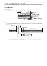
18.1.1 Summary
MR-J4-03A6(-RJ) servo amplifier is MELSERVO-J4 series 48 V DC and 24 V DC power compatible ultra-
small capacity servo amplifier.
The servo amplifier has position, speed, and torque control modes. In the position control mode, the
maximum pulse train of 4 Mpulses/s is supported. Further, it can perform operation with the control modes
switched, e.g. position/speed control, speed/torque control and torque/position control. Hence, it is
applicable to a wide range of fields, not only precision positioning and smooth speed control of machine tools
and general industrial machines but also line control and tension control.
With one-touch tuning and real-time auto tuning, you can automatically adjust the servo gains according to
the machine.
The following shows the differences with 100 W or more MR-J4-_A_(-RJ) servo amplifier.
Category Item
Differences
Related parameter
MR-J4-_A_(-RJ)
100 W or more
MR-J4-03A6(-RJ)
Power supply
Main circuit power supply
200 V AC/400 V AC/
100 V AC
48 V DC/24 V DC
[Pr. PC27]
Control circuit power supply
200 V AC/400 V AC/
100 V AC
24 V DC
Functional safety
STO function
Compatible
Encoder
Encoder resolution
4194304 pulses/rev
262144 pulses/rev
Status display
7-segment LED display digits 5-digits
3-digits [Pr.
PC36]
Analog monitor output
Output voltage range
± 10 V
5 V ± 4 V
[Pr. PC14]/[Pr. PC15]
Dynamic brake
Stop system
Stop with dynamic
brake
Stop with electronic
dynamic brake
[Pr. PF09]/[Pr. PF15]
Regenerative option
Regenerative option selection
Compatible
[Pr. PA02]
Operation mode
Fully closed loop control mode
Compatible
[Pr. PA01]
Linear servo motor control
mode
Compatible
DD motor control mode
Compatible
Function
SEMI-F47 function
Compatible
[Pr. PA20]/[Pr. PF25]
J3A electronic gear setting
value compatibility mode
Compatible
[Pr.
PA21]
Instantaneous power failure
tough drive
Compatible
[Pr. PA20]/[Pr. PF25]
Parameter unit
Compatible
[Pr. PF34]
Summary of Contents for MR-J4-100A(-RJ)
Page 19: ...10 MEMO ...
Page 75: ...1 FUNCTIONS AND CONFIGURATION 1 56 MEMO ...
Page 83: ...2 INSTALLATION 2 8 MEMO ...
Page 159: ...3 SIGNALS AND WIRING 3 76 MEMO ...
Page 203: ...4 STARTUP 4 44 MEMO ...
Page 351: ...7 SPECIAL ADJUSTMENT FUNCTIONS 7 40 MEMO ...
Page 365: ...8 TROUBLESHOOTING 8 14 MEMO ...
Page 387: ...9 DIMENSIONS 9 22 MEMO ...
Page 403: ...10 CHARACTERISTICS 10 16 MEMO ...
Page 553: ...12 ABSOLUTE POSITION DETECTION SYSTEM 12 30 MEMO ...
Page 567: ...13 USING STO FUNCTION 13 14 MEMO ...
Page 607: ...14 COMMUNICATION FUNCTION MITSUBISHI ELECTRIC GENERAL PURPOSE AC SERVO PROTOCOL 14 40 MEMO ...
Page 639: ...15 USING A LINEAR SERVO MOTOR 15 32 MEMO ...
Page 767: ...18 MR J4 03A6 RJ SERVO AMPLIFIER 18 84 MEMO ...
Page 856: ...APPENDIX App 41 ...
Page 905: ...MEMO ...

