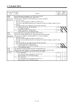


5. PARAMETERS
5 - 75
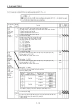
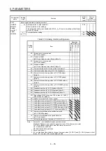
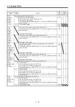
No./symbol/
name
Setting
digit
Function
Initial
value
[unit]
Control
mode
P S T
Po13
*OMOD1
MR-D01
analog
monitor 1
output
selection
Set a signal to output to Analog monitor 1.
_ _ x x Analog monitor 1 output selection
Refer to table 5.16 for settings.
This parameter setting is available with MR-J4-_A_-RJ servo amplifiers with software
version B7 or later.
00h
_ x _ _ For manufacturer setting
0h
x _ _ _
0h
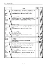
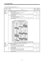
Table 5.16 Analog monitor setting value
Setting
value
Item
Operation
mode (Note 1)
Standard
F
ull.
Lin.
DD
_ _ 0 0 (Linear) servo motor speed
(±8 V/max. speed)
_ _ 0 1 Torque or thrust
(±8 V/max. torque or max. thrust) (Note 3)
_ _ 0 2 (Linear) servo motor speed
(+8 V/max. speed)
_ _ 0 3 Torque or thrust
(+8 V/max. torque or max. thrust) (Note 3)
_ _ 0 4 Current command (±8 V/max. current command)
_ _ 0 5 Command pulse frequency (±10 V/±4 Mpulses/s)
_ _ 0 6 Servo motor-side droop pulses (±10 V/100 pulses)
(Note 2)
_ _ 0 7 Servo motor-side droop pulses (±10 V/1000 pulses)
(Note 2)
_ _ 0 8 Servo motor-side droop pulses (±10 V/10000 pulses)
(Note 2)
_ _ 0 9 Servo motor-side droop pulses (±10 V/100000 pulses)
(Note 2)
_ _ 0 A Feedback position (±10 V/1 Mpulses) (Note 2)
_ _ 0 B Feedback position (±10 V/10 Mpulses) (Note 2)
_ _ 0 C Feedback position (±10 V/100 Mpulses) (Note 2)
_ _ 0 D Bus voltage (200 V class and 100 V class: +8 V/400 V,
400 V class: +8 V/800 V)
_ _ 0 E Speed command 2 (±8 V/max. speed)
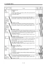
_ _ 1 0 Load-side droop pulses (±10 V/100 pulses) (Note 2)
_ _ 1 1 Load-side droop pulses (±10 V/1000 pulses) (Note 2)
_ _ 1 2 Load-side droop pulses (±10 V/10000 pulses) (Note 2)
_ _ 1 3 Load-side droop pulses (±10 V/100000 pulses) (Note 2)
_ _ 1 4 Load-side droop pulses (±10 V/1 M pulses) (Note 2)
_ _ 1 5 Servo motor-side/load-side position deviation
(±10 V/100000 pulses)
_ _ 1 6 Servo motor-side/load-side speed deviation
(±8 V/max. speed)
_ _ 1 7 Internal temperature of encoder (±10 V/±128 °C)
Note 1. Items with are available for each operation mode.
Standard: Standard (semi closed loop system) use of the rotary servo motor
Full.: Fully closed loop system use of the rotary servo motor
Lin.: Linear servo motor use
DD: Direct drive (DD) motor use
2.
Encoder pulse unit
3. 8 V is outputted at the maximum torque. However, when [Pr. PA11] and [Pr. PA12] are set to limit
torque, 8 V is output at the torque highly limited.
Summary of Contents for MR-J4-100A(-RJ)
Page 19: ...10 MEMO ...
Page 75: ...1 FUNCTIONS AND CONFIGURATION 1 56 MEMO ...
Page 83: ...2 INSTALLATION 2 8 MEMO ...
Page 159: ...3 SIGNALS AND WIRING 3 76 MEMO ...
Page 203: ...4 STARTUP 4 44 MEMO ...
Page 351: ...7 SPECIAL ADJUSTMENT FUNCTIONS 7 40 MEMO ...
Page 365: ...8 TROUBLESHOOTING 8 14 MEMO ...
Page 387: ...9 DIMENSIONS 9 22 MEMO ...
Page 403: ...10 CHARACTERISTICS 10 16 MEMO ...
Page 553: ...12 ABSOLUTE POSITION DETECTION SYSTEM 12 30 MEMO ...
Page 567: ...13 USING STO FUNCTION 13 14 MEMO ...
Page 607: ...14 COMMUNICATION FUNCTION MITSUBISHI ELECTRIC GENERAL PURPOSE AC SERVO PROTOCOL 14 40 MEMO ...
Page 639: ...15 USING A LINEAR SERVO MOTOR 15 32 MEMO ...
Page 767: ...18 MR J4 03A6 RJ SERVO AMPLIFIER 18 84 MEMO ...
Page 856: ...APPENDIX App 41 ...
Page 905: ...MEMO ...


