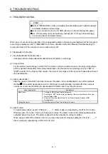

8. TROUBLESHOOTING
8 - 2
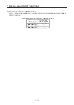
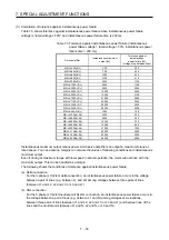
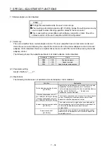
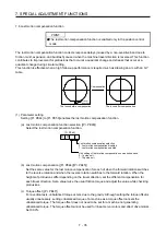
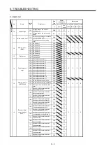
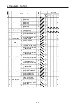
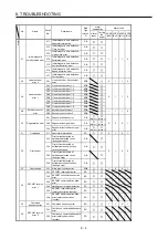
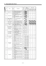
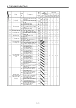
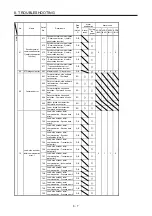
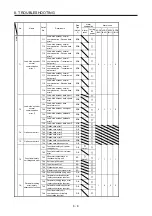
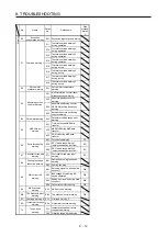
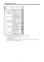
8.2 Alarm list
No. Name
Detail
No.
Detail name
Stop
Type
(Note 2,
3)
Alarm
deactivation
Alarm code
Alarm
reset
Cycling
the
power
ACD3
(Bit 3)
ACD2
(Bit 2)
ACD1
(Bit 1)
ACD0
(Bit 0)
Alarm
10 Undervoltage
10.1
Voltage drop in the control
circuit power
EDB
0 0 1 0
10.2
Voltage drop in the main circuit
power
SD
11
Switch setting error
11.1
Axis number setting error/station
number setting error
DB
11.2
Disabling control axis setting
error
DB
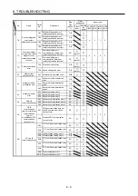
12.1 RAM error 1
DB
12.2 RAM error 2
DB
12
Memory error 1
(RAM)
12.3 RAM error 3
DB
0 0 0 0
12.4 RAM error 4
DB
12.5 RAM error 5
DB
12.6 RAM error 6
DB
13 Clock
error
13.1 Clock error 1
DB
0 0 0 0
13.2 Clock error 2
DB
14.1 Control process error 1
DB
14.2 Control process error 2
DB
14.3 Control process error 3
DB
14.4 Control process error 4
DB
Control process
error
14.5 Control process error 5
DB
0 0 0 0
14
14.6 Control process error 6
DB
14.7 Control process error 7
DB
14.8 Control process error 8
DB
14.9 Control process error 9
DB
14.A Control process error 10
DB
14.B Control process error 11
DB
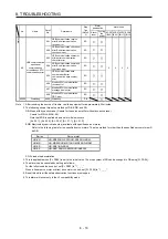
15
Memory error 2
(EEP-ROM)
15.1 EEP-ROM error at power on
DB
0 0 0 0
15.2 EEP-ROM error during operation
DB
15.4 Home position information read
error
DB
16
Encoder initial
communication
error 1
16.1
Encoder initial communication -
Receive data error 1
DB
0 1 1 0
16.2
Encoder initial communication -
Receive data error 2
DB
16.3
Encoder initial communication -
Receive data error 3
DB
16.4
Encoder initial communication -
Encoder malfunction (Note 6)
DB
16.5
Encoder initial communication -
Transmission data error 1
DB
16.6
Encoder initial communication -
Transmission data error 2
DB
16.7
Encoder initial communication -
Transmission data error 3
DB
16.8
Encoder initial communication -
Incompatible encoder (Note 6)
DB
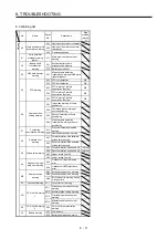
16.A
Encoder initial communication -
Process error 1
DB
16.B
Encoder initial communication -
Process error 2
DB
16.C
Encoder initial communication -
Process error 3
DB
16.D
Encoder initial communication -
Process error 4
DB
16.E
Encoder initial communication -
Process error 5
DB
16.F
Encoder initial communication -
Process error 6
DB
Summary of Contents for MR-J4-100A(-RJ)
Page 19: ...10 MEMO ...
Page 75: ...1 FUNCTIONS AND CONFIGURATION 1 56 MEMO ...
Page 83: ...2 INSTALLATION 2 8 MEMO ...
Page 159: ...3 SIGNALS AND WIRING 3 76 MEMO ...
Page 203: ...4 STARTUP 4 44 MEMO ...
Page 351: ...7 SPECIAL ADJUSTMENT FUNCTIONS 7 40 MEMO ...
Page 365: ...8 TROUBLESHOOTING 8 14 MEMO ...
Page 387: ...9 DIMENSIONS 9 22 MEMO ...
Page 403: ...10 CHARACTERISTICS 10 16 MEMO ...
Page 553: ...12 ABSOLUTE POSITION DETECTION SYSTEM 12 30 MEMO ...
Page 567: ...13 USING STO FUNCTION 13 14 MEMO ...
Page 607: ...14 COMMUNICATION FUNCTION MITSUBISHI ELECTRIC GENERAL PURPOSE AC SERVO PROTOCOL 14 40 MEMO ...
Page 639: ...15 USING A LINEAR SERVO MOTOR 15 32 MEMO ...
Page 767: ...18 MR J4 03A6 RJ SERVO AMPLIFIER 18 84 MEMO ...
Page 856: ...APPENDIX App 41 ...
Page 905: ...MEMO ...


