
A - 6
(5) Corrective actions
CAUTION
Ensure safety by confirming the power off, etc. before performing corrective actions. Otherwise, it may
cause an accident.
If it is assumed that a power failure, machine stoppage, or product malfunction may result in a hazardous
situation, use a servo motor with an electromagnetic brake or provide an external brake system for
holding purpose to prevent such hazard.
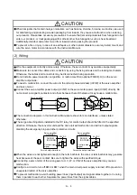
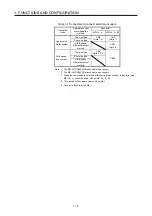
Configure an electromagnetic brake circuit which is interlocked with an external emergency stop switch.
Servo motor
Electromagnetic brake
B
RA
Contacts must be opened with
the emergency stop switch.
Contacts must be opened when ALM
(Malfunction) or MBR (Electromagnetic
brake interlock) turns off.
24 V DC
When an alarm occurs, eliminate its cause, ensure safety, and deactivate the alarm to restart operation.
If the molded-case circuit breaker or fuse is activated, be sure to remove the cause and secure safety
before switching the power on. If necessary, replace the servo amplifier and recheck the wiring.
Otherwise, it may cause smoke, fire, or an electric shock.
Provide an adequate protection to prevent unexpected restart after an instantaneous power failure.
After an earthquake or other natural disasters, ensure safety by checking the conditions of the
installation, mounting, wiring, and equipment before switching the power on to prevent an electric shock,
injury, or fire.
(6) Maintenance, inspection and parts replacement
CAUTION
Make sure that the emergency stop circuit operates properly such that an operation can be stopped
immediately and a power is shut off by the emergency stop switch.
It is recommended that the servo amplifier be replaced every 10 years when it is used in general
environment.
When using the servo amplifier that has not been energized for an extended period of time, contact your
local sales office.
(7) General instruction
To illustrate details, the equipment in the diagrams of this Instruction Manual may have been drawn
without covers and safety guards. When the equipment is operated, the covers and safety guards must
be installed as specified. Operation must be performed in accordance with this Instruction Manual.
Summary of Contents for MR-J4-100A(-RJ)
Page 19: ...10 MEMO ...
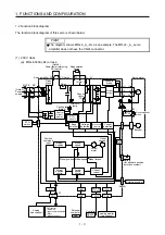
Page 75: ...1 FUNCTIONS AND CONFIGURATION 1 56 MEMO ...
Page 83: ...2 INSTALLATION 2 8 MEMO ...
Page 159: ...3 SIGNALS AND WIRING 3 76 MEMO ...
Page 203: ...4 STARTUP 4 44 MEMO ...
Page 351: ...7 SPECIAL ADJUSTMENT FUNCTIONS 7 40 MEMO ...
Page 365: ...8 TROUBLESHOOTING 8 14 MEMO ...
Page 387: ...9 DIMENSIONS 9 22 MEMO ...
Page 403: ...10 CHARACTERISTICS 10 16 MEMO ...
Page 553: ...12 ABSOLUTE POSITION DETECTION SYSTEM 12 30 MEMO ...
Page 567: ...13 USING STO FUNCTION 13 14 MEMO ...
Page 607: ...14 COMMUNICATION FUNCTION MITSUBISHI ELECTRIC GENERAL PURPOSE AC SERVO PROTOCOL 14 40 MEMO ...
Page 639: ...15 USING A LINEAR SERVO MOTOR 15 32 MEMO ...
Page 767: ...18 MR J4 03A6 RJ SERVO AMPLIFIER 18 84 MEMO ...
Page 856: ...APPENDIX App 41 ...
Page 905: ...MEMO ...


