


3. SIGNALS AND WIRING
3 - 65
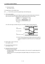
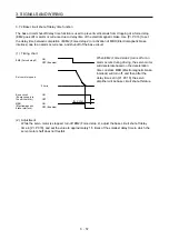
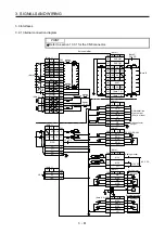
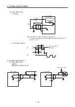
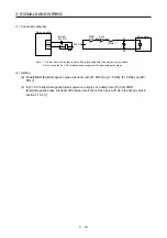
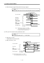
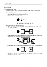
(b) Open-collector type
1) Interface
Approximately
1.2 k
Ω
Servo amplifier
24 V DC
OPC
PP, NP
DOCOM
SD
Max. input pulse
frequency 200 kpulses/s
2 m or less
(Note)
Note. Pulse train input interface is comprised of a photocoupler.
If a resistor is connected to the pulse train signal line, it may malfunction due to
reduction in current.
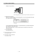
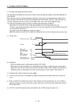
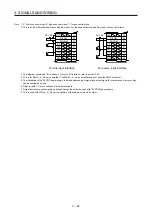
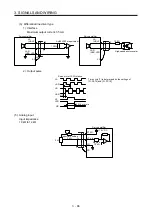
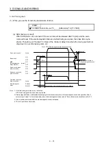
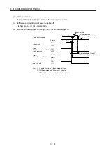
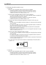
2) Input pulse condition
0.9
0.1
tc
tLH
tc
tHL
tF
PP
NP
tLH = tHL < 0.2 s
tc > 2 s
tF > 3 s
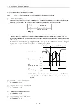
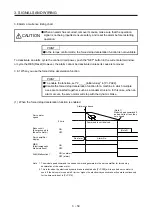
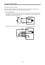
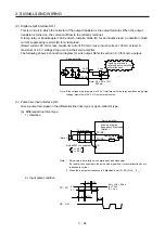
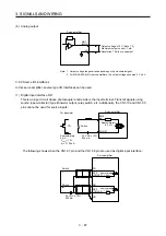
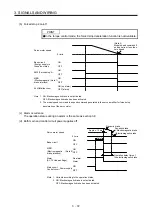
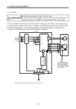
(4) Encoder output pulse DO-2
(a) Open-collector type
Interface
Maximum sink current: 35 mA
Photocoupler
Servo amplifier
OP
LG
SD
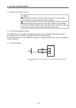
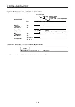
Servo amplifier
OP
LG
SD
5 V DC to 24 V DC
Summary of Contents for MR-J4-100A(-RJ)
Page 19: ...10 MEMO ...
Page 75: ...1 FUNCTIONS AND CONFIGURATION 1 56 MEMO ...
Page 83: ...2 INSTALLATION 2 8 MEMO ...
Page 159: ...3 SIGNALS AND WIRING 3 76 MEMO ...
Page 203: ...4 STARTUP 4 44 MEMO ...
Page 351: ...7 SPECIAL ADJUSTMENT FUNCTIONS 7 40 MEMO ...
Page 365: ...8 TROUBLESHOOTING 8 14 MEMO ...
Page 387: ...9 DIMENSIONS 9 22 MEMO ...
Page 403: ...10 CHARACTERISTICS 10 16 MEMO ...
Page 553: ...12 ABSOLUTE POSITION DETECTION SYSTEM 12 30 MEMO ...
Page 567: ...13 USING STO FUNCTION 13 14 MEMO ...
Page 607: ...14 COMMUNICATION FUNCTION MITSUBISHI ELECTRIC GENERAL PURPOSE AC SERVO PROTOCOL 14 40 MEMO ...
Page 639: ...15 USING A LINEAR SERVO MOTOR 15 32 MEMO ...
Page 767: ...18 MR J4 03A6 RJ SERVO AMPLIFIER 18 84 MEMO ...
Page 856: ...APPENDIX App 41 ...
Page 905: ...MEMO ...


