


11. OPTIONS AND PERIPHERAL EQUIPMENT
11 - 16
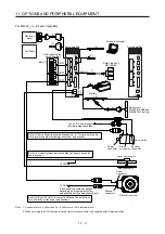
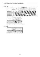
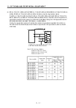
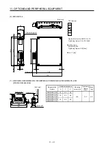
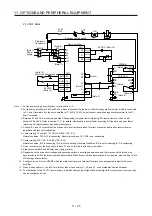
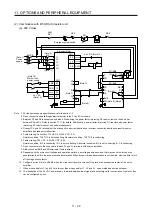
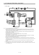
(3) MR-J4-11KA(-RJ) to MR-J4-22KA(-RJ)/MR-J4-11KA4(-RJ) to MR-J4-22KA4(-RJ) (when using the
supplied regenerative resistor)
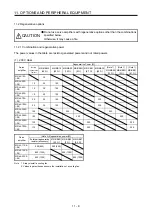
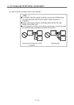
CAUTION
The regenerative resistor supplied with 11 kW to 22 kW servo amplifiers does not
have a protective cover. Touching the resistor (including wiring/screw hole area)
may cause a burn injury and electric shock. Even if the power was shut-off, be
careful until the bus voltage discharged and the temperature decreased because
of the following reasons.
It may cause a burn injury due to very high temperature without cooling.
It may cause an electric shock due to charged capacitor of the servo amplifier.
Do not use servo amplifiers with external regenerative resistors other than the
combinations specified below. Otherwise, it may cause a fire.
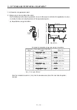
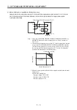
When using the regenerative resistors supplied to the servo amplifier, the specified number of resistors
(4 or 5 resistors) must be connected in series. If they are connected in parallel or in less than the
specified number, the servo amplifier may become faulty and/or the regenerative resistors burn.
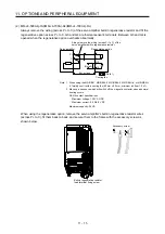
Install the resistors at intervals of about 70 mm. Cooling the resistors with two cooling fans (1.0 m
3
/min
or more, 92 mm × 92 mm) improves the regeneration capability. In this case, set "_ _ F A" in [Pr. PA02].
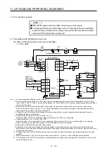
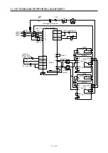
P+
C
Servo amplifier
Cooling fan
(Note)
Series connection
5 m or shorter
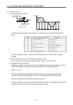
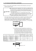
Note. The number of resistors connected in series depends on the resistor type. The
thermal sensor is not mounted on the attached regenerative resistor. An abnormal
heating of resistor may be generated at a regenerative circuit failure. Install a thermal
sensor near the resistor and establish a protective circuit to shut off the main circuit
power supply when abnormal heating occurs. The detection level of the thermal
sensor varies according to the settings of the resistor. Set the thermal sensor in the
most appropriate position on your design basis, or use the thermal sensor built-in
regenerative option. (MR-RB5R, MR-RB9F, MR-RB9T, MR-RB5K-4, or MR-RB6K-4)
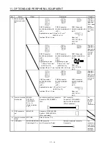
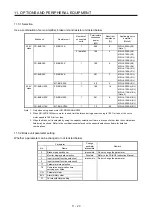
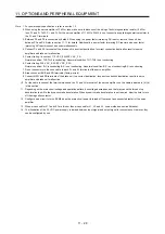
Servo amplifier
Regenerative resistor
Symbol (Note)
Regenerative power [W]
Resultant
resistance [
Ω
]
Number of
resistors
Normal Cooling
MR-J4-11KA(-RJ) GRZG400-0.8
Ω
GR400
R80K 500
800
3.2
4
MR-J4-15KA(-RJ) GRZG400-0.6
Ω
GR400
R60K
850 1300
3
5
MR-J4-22KA(-RJ) GRZG400-0.5
Ω
GR400
R50K
2.5
MR-J4-11KA4(-RJ) GRZG400-2.5
Ω
GR400
2R5K 500
800
10
4
MR-J4-15KA4(-RJ)
MR-J4-22KA4(-RJ)
GRZG400-2
Ω
GR400
2R0K 850 1300 10
5
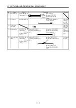
Note. The following shows an indication example of symbol.
GR400 R80K
Symbol
Regenerative resistor
Summary of Contents for MR-J4-100A(-RJ)
Page 19: ...10 MEMO ...
Page 75: ...1 FUNCTIONS AND CONFIGURATION 1 56 MEMO ...
Page 83: ...2 INSTALLATION 2 8 MEMO ...
Page 159: ...3 SIGNALS AND WIRING 3 76 MEMO ...
Page 203: ...4 STARTUP 4 44 MEMO ...
Page 351: ...7 SPECIAL ADJUSTMENT FUNCTIONS 7 40 MEMO ...
Page 365: ...8 TROUBLESHOOTING 8 14 MEMO ...
Page 387: ...9 DIMENSIONS 9 22 MEMO ...
Page 403: ...10 CHARACTERISTICS 10 16 MEMO ...
Page 553: ...12 ABSOLUTE POSITION DETECTION SYSTEM 12 30 MEMO ...
Page 567: ...13 USING STO FUNCTION 13 14 MEMO ...
Page 607: ...14 COMMUNICATION FUNCTION MITSUBISHI ELECTRIC GENERAL PURPOSE AC SERVO PROTOCOL 14 40 MEMO ...
Page 639: ...15 USING A LINEAR SERVO MOTOR 15 32 MEMO ...
Page 767: ...18 MR J4 03A6 RJ SERVO AMPLIFIER 18 84 MEMO ...
Page 856: ...APPENDIX App 41 ...
Page 905: ...MEMO ...


