
8. TROUBLESHOOTING
8 - 1
8. TROUBLESHOOTING
POINT
Refer to "MELSERVO-J4 Servo Amplifier Instruction Manual (Troubleshooting)"
for details of alarms and warnings.
As soon as an alarm occurs, turn SON (Servo-on) off and interrupt the power.
[AL. 37 Parameter error] and warnings (except [AL. F0 Tough drive warning])
are not recorded in the alarm history.
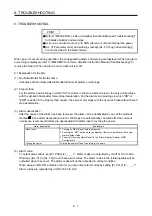
When an error occurs during operation, the corresponding alarm and warning are displayed. When an alarm
or warning is displayed, refer to "MELSERVO-J4 Servo Amplifier Instruction Manual (Troubleshooting)" to
remove the failure. When an alarm occurs, ALM will turn off.
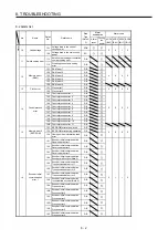
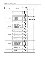
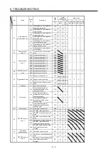
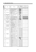
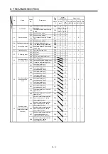
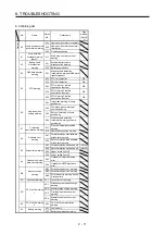
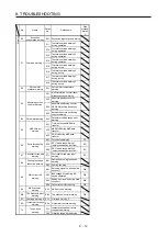
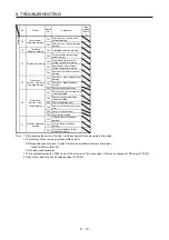
8.1 Explanation for the lists
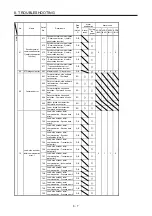
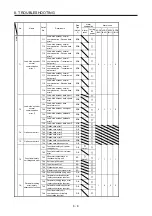
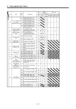
(1) No./Name/Detail No./Detail name
Indicates each No./Name/Detail No./Detail name of alarms or warnings.
(2) Stop method
For the alarms and warnings in which "SD" is written in the stop method column, the servo motor stops
with the dynamic brake after forced stop deceleration. For the alarms and warnings in which "DB" or
"EDB" is written in the stop method column, the servo motor stops with the dynamic brake without forced
stop deceleration.
(3) Alarm deactivation
After the cause of the alarm has been removed, the alarm can be deactivated by any of the methods
marked in the alarm deactivation column. Warnings are automatically canceled after the cause of
occurrence is removed. Alarms are deactivated with alarm reset or cycling the power.
Alarm deactivation
Explanation
Alarm reset
1. Turning on RES (Reset) with input device
2. Pushing the "SET" button while the display of the servo amplifier is the current
alarm display status
3. Pushing "Occurring Alarm Reset" in the "Alarm Display" window of MR
Configurator2
Cycling the power
Turning the power off and then turning it on again.
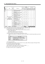
(4) Alarm code
To output alarm codes, set [Pr. PD34] to "_ _ _ 1". Alarm codes are outputted by on/off of bit 0 to bit 2.
Warnings ([AL. 91] to [AL. F3]) do not have alarm codes. The alarm codes in the following table will be
outputted when they occur. The alarm codes will not be outputted in normal condition.
When using an MR-D01 extension IO unit, you can output alarm codes by setting [Pr. Po12] to "_ _ _ 1".
Alarm codes are outputted by on/off of bit 0 to bit 3.
Summary of Contents for MR-J4-100A(-RJ)
Page 19: ...10 MEMO ...
Page 75: ...1 FUNCTIONS AND CONFIGURATION 1 56 MEMO ...
Page 83: ...2 INSTALLATION 2 8 MEMO ...
Page 159: ...3 SIGNALS AND WIRING 3 76 MEMO ...
Page 203: ...4 STARTUP 4 44 MEMO ...
Page 351: ...7 SPECIAL ADJUSTMENT FUNCTIONS 7 40 MEMO ...
Page 365: ...8 TROUBLESHOOTING 8 14 MEMO ...
Page 387: ...9 DIMENSIONS 9 22 MEMO ...
Page 403: ...10 CHARACTERISTICS 10 16 MEMO ...
Page 553: ...12 ABSOLUTE POSITION DETECTION SYSTEM 12 30 MEMO ...
Page 567: ...13 USING STO FUNCTION 13 14 MEMO ...
Page 607: ...14 COMMUNICATION FUNCTION MITSUBISHI ELECTRIC GENERAL PURPOSE AC SERVO PROTOCOL 14 40 MEMO ...
Page 639: ...15 USING A LINEAR SERVO MOTOR 15 32 MEMO ...
Page 767: ...18 MR J4 03A6 RJ SERVO AMPLIFIER 18 84 MEMO ...
Page 856: ...APPENDIX App 41 ...
Page 905: ...MEMO ...


