


APPENDIX
App. - 42
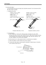
App. 7 Analog monitor
POINT
A voltage of analog monitor output may be irregular at power-on.
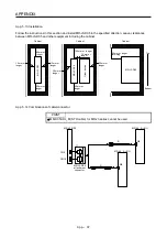
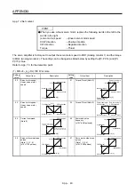
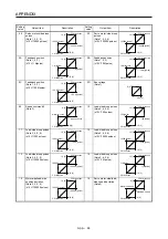
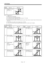
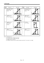
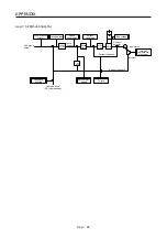
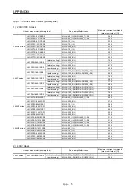
The servo status can be output to two channels in terms of voltage.
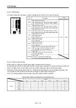
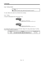
App. 7.1 Setting
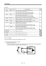
Change the following digits of [Pr. PC14] and [Pr. PC15].
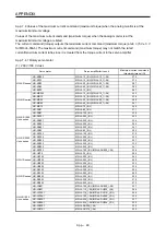
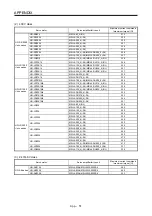
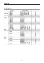
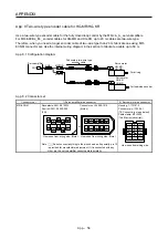
Analog monitor 1 output selection
(the signal provided to the output across MO1 and LG)
0 0
[Pr. PC14]
Analog monitor 2 output selection
(the signal provided to the output across MO2 and LG)
0 0
[Pr. PC15]
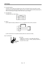
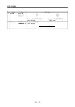
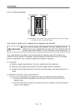
[Pr. PC39] and [Pr. PC40] can be used to set the offset voltages to the analog output voltages. The setting
range is between -9999 mV and 9999 mV.
Parameter
Description
Setting range [mV]
PC39
This is used to set the offset voltage of MO1 (Analog monitor 1).
-9999 to 9999
PC40
This is used to set the offset voltage of MO2 (Analog monitor 2).
Summary of Contents for MR-J4-100A(-RJ)
Page 19: ...10 MEMO ...
Page 75: ...1 FUNCTIONS AND CONFIGURATION 1 56 MEMO ...
Page 83: ...2 INSTALLATION 2 8 MEMO ...
Page 159: ...3 SIGNALS AND WIRING 3 76 MEMO ...
Page 203: ...4 STARTUP 4 44 MEMO ...
Page 351: ...7 SPECIAL ADJUSTMENT FUNCTIONS 7 40 MEMO ...
Page 365: ...8 TROUBLESHOOTING 8 14 MEMO ...
Page 387: ...9 DIMENSIONS 9 22 MEMO ...
Page 403: ...10 CHARACTERISTICS 10 16 MEMO ...
Page 553: ...12 ABSOLUTE POSITION DETECTION SYSTEM 12 30 MEMO ...
Page 567: ...13 USING STO FUNCTION 13 14 MEMO ...
Page 607: ...14 COMMUNICATION FUNCTION MITSUBISHI ELECTRIC GENERAL PURPOSE AC SERVO PROTOCOL 14 40 MEMO ...
Page 639: ...15 USING A LINEAR SERVO MOTOR 15 32 MEMO ...
Page 767: ...18 MR J4 03A6 RJ SERVO AMPLIFIER 18 84 MEMO ...
Page 856: ...APPENDIX App 41 ...
Page 905: ...MEMO ...


