16. USING A DIRECT DRIVE MOTOR
16 - 6
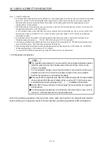
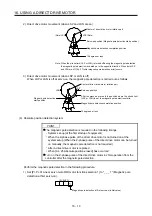
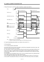
Note 1. Use MR Configurator2.
2. For the absolute position detection system, always turn on the Z-phase pulse of the direct drive motor while the servo amplifier
power is on, and then turn the servo amplifier power supply off and on again. By turning off and on the power supply, the
absolute position becomes confirmed. Without this operation, the absolute position will not be regained properly, and a
warning will occur at the controller.
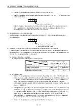
3 If the Z-phase pulse of the direct drive motor can be turned on manually, the Z-phase pulse does not have to be turned on by
the magnetic pole detection or the JOG operation.
For this operation, always connect the direct drive motor encoder and the servo amplifier, and turn on only the control circuit
power supply of the servo amplifier (L11/L21) (turn off the main circuit power supply L1/L2/L3). Perform this operation by
considering the safety.
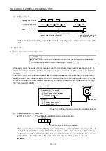
4. Test operation cannot be performed in the absolute position detection system, either. To perform test operation, select
"Disabled (incremental system) (_ _ _ 0)" in [Pr. PA03]. Refer to section 16.3.2 (1) for details.
5.
After the servo amplifier is connected to the direct drive motor with an encoder cable, [AL. 25 Absolute position erased] will
occur at the first power on. Cancel the alarm by turning on/off the power.
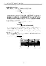
6. When the magnetic pole detection is performed with absolute position detection system by DIO transfer, [AL. 93 ABS data
transfer warning] will occur. Refer to section 16.4 for details.
7. To cancel [AL. 93 ABS data transfer warning], cycle SON (Servo-on) or set a home position.
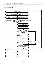
16.3.2 Magnetic pole detection
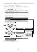
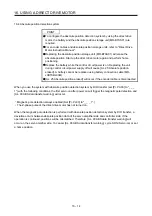
POINT
The magnetic pole detection is not required for the configured absolute position
detection system where the Z-phase pulse of the direct drive motor can be
turned on manually.
For this operation, always connect the direct drive motor encoder and the servo
amplifier and turn on the control circuit power supply of the servo amplifier.
Perform this operation by considering the safety.
When performing a magnetic pole detection without using LSP (Forward rotation
stroke end) and LSN (Reverse rotation stroke end), set [Pr. PL08 Linear servo
motor/DD motor function selection 3] to "_ 1 _ _" to disable LSP and LSN.
Set [Pr. PE47 Torque offset] to "0 (initial value)" before executing the magnetic
pole detection.
For the magnetic pole detection of vertical axis with direct drive motors, refer to
section 2.1 of "Direct Drive Motor Instruction Manual".
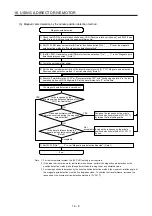
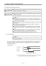
Before the positioning operation of the direct drive motor, make sure to perform the magnetic pole detection.
Before starting up the equipment, perform the test operation (positioning operation) of MR Configurator2.
Summary of Contents for MR-J4-100A(-RJ)
Page 19: ...10 MEMO ...
Page 75: ...1 FUNCTIONS AND CONFIGURATION 1 56 MEMO ...
Page 83: ...2 INSTALLATION 2 8 MEMO ...
Page 159: ...3 SIGNALS AND WIRING 3 76 MEMO ...
Page 203: ...4 STARTUP 4 44 MEMO ...
Page 351: ...7 SPECIAL ADJUSTMENT FUNCTIONS 7 40 MEMO ...
Page 365: ...8 TROUBLESHOOTING 8 14 MEMO ...
Page 387: ...9 DIMENSIONS 9 22 MEMO ...
Page 403: ...10 CHARACTERISTICS 10 16 MEMO ...
Page 553: ...12 ABSOLUTE POSITION DETECTION SYSTEM 12 30 MEMO ...
Page 567: ...13 USING STO FUNCTION 13 14 MEMO ...
Page 607: ...14 COMMUNICATION FUNCTION MITSUBISHI ELECTRIC GENERAL PURPOSE AC SERVO PROTOCOL 14 40 MEMO ...
Page 639: ...15 USING A LINEAR SERVO MOTOR 15 32 MEMO ...
Page 767: ...18 MR J4 03A6 RJ SERVO AMPLIFIER 18 84 MEMO ...
Page 856: ...APPENDIX App 41 ...
Page 905: ...MEMO ...

