7. SPECIAL ADJUSTMENT FUNCTIONS
7 - 33
(3) Calculation of tolerance against instantaneous power failure
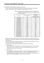
Table 7.3 shows tolerance against instantaneous power failure when instantaneous power failure
voltage is "rated voltage × 50%" and instantaneous power failure time is 200 ms.
Table 7.3 Tolerance against instantaneous power failure (instantaneous
power failure voltage = rated voltage × 50%, instantaneous power
failure time = 200 ms)
Servo amplifier
Instantaneous maximum
output [W]
Tolerance against
instantaneous
power failure [W]
(voltage drop between lines)
MR-J4-10A(-RJ) 350
250
MR-J4-20A(-RJ) 700
420
MR-J4-40A(-RJ) 1400
630
MR-J4-60A(-RJ) 2100
410
MR-J4-70A(-RJ) 2625
1150
MR-J4-100A(-RJ) 3000
1190
MR-J4-200A(-RJ) 5400
2040
MR-J4-350A(-RJ) 10500
2600
MR-J4-500A(-RJ) 15000
4100
MR-J4-700A(-RJ) 21000
5900
MR-J4-11KA(-RJ) 40000
2600
MR-J4-15KA(-RJ) 50000
3500
MR-J4-22KA(-RJ) 56000
4300
MR-J4-60A4(-RJ) 1900
190
MR-J4-100A4(-RJ) 3500
200
MR-J4-200A4(-RJ) 5400
350
MR-J4-350A4(-RJ) 10500
730
MR-J4-500A4(-RJ) 15000
890
MR-J4-700A4(-RJ) 21000
1500
MR-J4-11KA4(-RJ) 40000
2400
MR-J4-15KA4(-RJ) 50000
3200
MR-J4-22KA4(-RJ) 56000
4200
Instantaneous maximum output means power which servo amplifier can output in maximum torque at
rated speed. You can examine margins to compare the values of following conditions and instantaneous
maximum output.
Even if driving at maximum torque with low speed in actual operation, the motor will not drive with the
maximum output. This can be handled as a margin.
The following shows the conditions of tolerance against instantaneous power failure.
(a) Delta connection
For the 3-phase (L1/L2/L3) delta connection, an instantaneous power failure occurs in the voltage
between a pair of lines (e.g. between L1 and L2) among voltages between three pairs of lines
(between L1 and L2, L2 and L3, or L3 and L1).
(b) Star connection
For the 3-phase (L1/L2/L3/neutral point N) star connection, an instantaneous power failure occurs in
the voltage between a pair of lines (e.g. between L1 and N) among voltages at six locations,
between three pairs of lines (between L1 and L2, L2 and L3, or L3 and L1) and between one of the
lines and the neutral point (between L1 and N, L2 and N, or L3 and N).
Summary of Contents for MR-J4-100A(-RJ)
Page 19: ...10 MEMO ...
Page 75: ...1 FUNCTIONS AND CONFIGURATION 1 56 MEMO ...
Page 83: ...2 INSTALLATION 2 8 MEMO ...
Page 159: ...3 SIGNALS AND WIRING 3 76 MEMO ...
Page 203: ...4 STARTUP 4 44 MEMO ...
Page 351: ...7 SPECIAL ADJUSTMENT FUNCTIONS 7 40 MEMO ...
Page 365: ...8 TROUBLESHOOTING 8 14 MEMO ...
Page 387: ...9 DIMENSIONS 9 22 MEMO ...
Page 403: ...10 CHARACTERISTICS 10 16 MEMO ...
Page 553: ...12 ABSOLUTE POSITION DETECTION SYSTEM 12 30 MEMO ...
Page 567: ...13 USING STO FUNCTION 13 14 MEMO ...
Page 607: ...14 COMMUNICATION FUNCTION MITSUBISHI ELECTRIC GENERAL PURPOSE AC SERVO PROTOCOL 14 40 MEMO ...
Page 639: ...15 USING A LINEAR SERVO MOTOR 15 32 MEMO ...
Page 767: ...18 MR J4 03A6 RJ SERVO AMPLIFIER 18 84 MEMO ...
Page 856: ...APPENDIX App 41 ...
Page 905: ...MEMO ...

